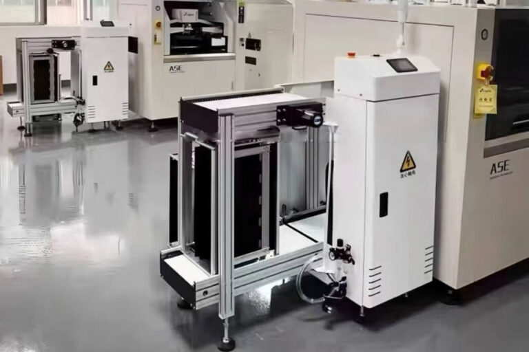
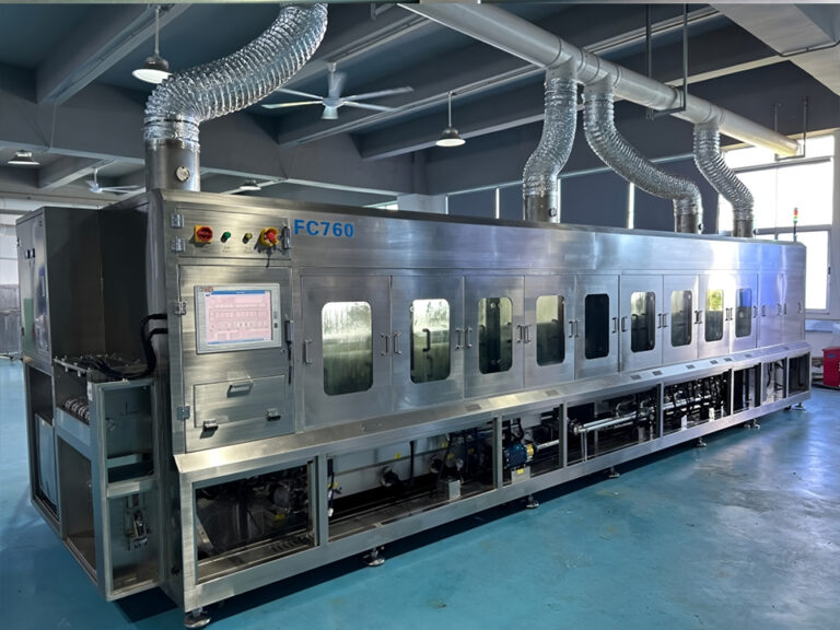
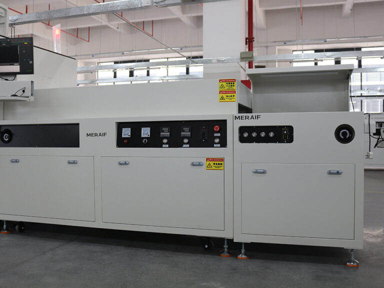
Cobot integration with SMT loaders, trays, and PCB handling systems is less about buying an arm and more about connecting three things that were designed separately: the robot, the carriers it touches (magazines, racks, component trays, boards), and an SMT line that expects boards to arrive in a defined way. When those interfaces are specified well, a collaborative robot can tend magazines, move boards between stations, and handle trays without a full guarding cage. When they are not, the cell stalls at the first warped board, mismatched magazine, or missing handover signal. This guide explains where cobots fit in SMT board handling, what to verify mechanically, electrically, and for safety, and what to prepare before asking suppliers for a quote.
What Does Cobot Integration Cover in an SMT Line?
In an SMT line, cobot integration means making a collaborative robot cooperate with board-handling equipment on three layers at once:
- Physical layer: the robot’s reach, mounting height, gripper, and the fixtures that locate magazines, racks, or trays.
- Signal layer: the handshake that tells a loader, conveyor, or placement machine that a board is available or that the next machine is ready.
- Data layer: board identity, pass/fail status, and traceability records that must survive the handover.
Typical cobot tasks include loading full magazines into a loader and removing empty ones, picking boards from a rack onto a conveyor, moving finished boards from an unloader to test or packing, and feeding component trays to a machine or kitting station. Each task stresses the three layers differently, so the first step is to define which task you are automating rather than asking whether “a cobot” fits the line.
Cobot or Dedicated Loader: Which Do You Actually Need?
A common assumption is that adding a cobot upgrades PCB handling. Often it does not. A standard inline magazine loader or unloader already does one job at line speed and usually arrives with a native board-transfer interface. A cobot earns its cost when the task around the loader is variable: frequent magazine swaps, several magazine or board formats, tray stacks, or transfers between lines. If the line runs one board family in one magazine format for long runs, a dedicated loader with a simple magazine cart can be cheaper, faster, and easier to validate.
The comparison below is qualitative. It describes where each approach tends to fit, not measured performance.
| Approach | Best fit | Main constraint | What to verify |
|---|---|---|---|
| Dedicated inline loader/unloader only | Stable board sizes, manual magazine exchange acceptable | An operator still exchanges magazines | Board size range, magazine format, handover interface |
| Cobot tending magazines for a loader/unloader | Frequent magazine exchanges, unattended periods, mixed magazine stock | Magazine positioning, staging capacity, safety design | Magazine fixtures, loader magazine-change sensing, rack reach |
| Cobot picking boards directly to a conveyor | Low-volume, high-mix work or lines without a loader | Gripper contact with boards, ESD, board bow, per-board cycle time | Gripper type, component keep-out zones, handover logic |
| Cobot handling component trays | Tray stacks, kitting, feeding tray-based machines | Tray warpage, pocket orientation, moisture-sensitive part handling | Tray dimensions, stacking method, machine tray-loading mechanism |
The cobot approach holds up best in high-mix work, but only when changeover is quick. If swapping grippers, fixtures, and programs takes longer than the manual task it replaced, flexibility on paper does not translate into output.
Mechanical Integration: Magazines, Boards, and Trays
How should a cobot handle PCB magazines and racks?
A cobot should place magazines against fixed locating features, not rely on free-space positioning alone. Magazines vary between suppliers, wear over time, and can be bent or loaded unevenly. The cell therefore needs datum stops or guides, plus a way to confirm that a magazine is present, correctly oriented, and seated before the loader lifts it.
Several variables determine whether this works:
- Slot pitch and magazine width settings: the loader’s adjustment range and the cobot’s fixture both have to cover your actual magazines.
- Cumulative accuracy: a cobot’s published repeatability describes the arm alone. Gripper compliance, fixture tolerance, and magazine variation all add to the error at the loader.
- Staging capacity: how many magazines the cell can hold between operator visits.
- Transfer height: the SMEMA mechanical specification as summarized on Wikipedia gives an adjustable conveyor height of 940 to 965 mm. Confirm the figure against your machines’ documentation and plan the cobot base or pedestal around it.
Ask the supplier what happens when a magazine is misloaded or a board protrudes from a slot. A cell that stops and reports is acceptable. A cell that continues and crushes a board is not.
Which gripper suits PCBs: edge gripping or vacuum?
Neither is universally better. Edge gripping avoids touching board surfaces but needs clearance from components near the board edge, so it depends on the component keep-out zone in the design. Vacuum pick-up needs a clean, flat contact area and becomes difficult on boards populated on both sides.
Other variables matter as well:
- Board state: printed, placed, reflowed, or bare boards are different handling cases. Paste-printed surfaces should not be touched, and boards at an unloader may still be warm, so check temperature at the pick point.
- Warpage: thin or bowed boards can miss a slot or jam at a conveyor entrance.
- Payload: the rated payload must cover the gripper, any adapter, and a full board or magazine.
- Changeover: adjustable or quick-change grippers cost more but reduce downtime for mixed board families.
What should buyers check for tray handling?
Component trays introduce different failure modes from boards. Verify tray dimensions and warpage, stacking orientation, pocket orientation, and how the receiving machine accepts a tray, whether through a stack, a drawer, or a changer. If trays hold moisture-sensitive devices, confirm that the cell does not extend floor-exposure time beyond what your component supplier and process allow. Tray-handling cells also need a rule for partially used trays, otherwise the cobot may mix them back into full stock.
ESD control inside the cell
Everything that touches boards or components is part of the ESD control picture. The ANSI/ESD S20.20-2021 standard, as described by ANSI, provides technical requirements for implementing and maintaining an ESD control program covering electronic items susceptible to discharge at or above 100 V HBM, 200 V CDM, and 35 V on isolated conductors. For a cobot cell, that translates into questions about gripper pad materials, magazine and tray materials, grounding paths through the arm and mounts, and whether the cell’s materials match your existing ESD program. Request material and grounding documentation rather than accepting a general “ESD-safe” label.
Signal and Data Integration: SMEMA, Hermes, and Traceability
A cobot arm is not an SMT machine, so it does not automatically speak the language of the line. The supplier of the cell, usually through a PLC or controller, has to provide the handover signals. Confirm who writes that logic before comparing quotes.
SMEMA is the long-standing hardware handshake. According to the SMEMA overview on Wikipedia, it uses a “Board Available” and a “Machine Ready” signal, with a “Failed Board Available” signal as optional, and it has no addressing. The Hermes Standard Q&A describes IPC-HERMES-9852 as the next-generation standard for board flow data management and handover, and it describes IPC-CFX as complementing it by connecting the SMT line to an MES. Older machines on your line may offer only SMEMA, while newer ones may support Hermes.
For buyers, three questions follow:
- Which interface does each neighbouring machine support, and does the cobot cell need to emulate more than one?
- How does the cell treat a board flagged as failed? If your line segregates NG boards, the cobot must route them correctly and keep their identity.
- If you track boards by barcode or serial number, where is the identity read, and does the cobot’s handling step ever break the link between board and record?
Safety: Collaborative Application, Not Collaborative Robot
A cobot does not make a cell safe on its own. Per A3’s FAQ on the updated ISO 10218 series, ISO/TS 15066:2016 content has been incorporated into ISO 10218-2:2025, and the revised standards use “collaborative application” in place of “collaborative robot,” because only the actual use of the robot can be designed, tested, and confirmed as collaborative. The same source notes that the robot application includes the workpieces, the task program, and supporting machinery and equipment.
In SMT handling, that scope matters. Sharp board edges, heavy magazine stacks, gripper pinch points, and the gap between a magazine and a loader lift are part of the assessment. Safety functions can be built into the robot or supplied by protective devices, or a combination, so a quote should state which approach is used.
Safety design also affects throughput. If a cell slows or stops when a person approaches, the arm’s rated speed is not the speed you get. Ask the integrator for the risk assessment summary and the cycle time achieved under the safety configuration, and check local regulatory requirements for your installation region.
Does the Cobot Need to Be Fast? An Illustrative Calculation
Not always. Consider a hypothetical line that produces one board every 30 seconds, fed by magazines holding 30 boards. A loader empties a magazine every 15 minutes (30 boards × 30 seconds). A cobot tending magazines has several minutes to exchange one, so reliability and staging capacity matter more than arm speed. Now consider the same line fed directly by a cobot picking one board at a time. Every pick, place, and handshake must fit inside 30 seconds, including any safety slowdowns. The same robot is comfortable in the first role and marginal in the second.
This example is illustrative only. Use your own takt time, magazine capacity, and board mix when comparing options.
Maintenance: Lubrication Points in the Handling Cell
A cobot cell adds moving axes: external linear tracks, magazine lifts, pushers, and pedestals, alongside the loader and placement machine axes already on the line. Lubrication is a maintenance interface and should not be a selection criterion for the cobot itself. For the arm’s own joints, follow the cobot manufacturer’s maintenance manual and do not substitute a general-purpose grease.
Precision axes: ball screws and linear guides
Match lubricant to the machine builder’s specification. For Panasonic placement equipment, the Panasonic MP grease for SMT machinery page lists ball screws, bearings, and linear guides as applications, a synthetic base oil, a −54 °C to +177 °C range, and several Panasonic model codes. Verify those codes against your machine’s maintenance documentation before ordering.
For other precision axes, the supplier’s pages list two synthetic-based options. NS1-4 grease for bearings, ball screws, and sliding guides is listed with a synthetic formulation and a typical range of −40 °C to +160 °C, while OKS 470 grease for precision machine components is listed as a synthetic/mineral blend with a typical range of −40 °C to +150 °C.
General-purpose lubrication points
The pages for OKS 402 industrial grease, OKS 250 premium industrial grease, and NS2(2)-7 industrial grease describe mineral-oil-based NLGI 2 greases aimed at heavy machinery, automotive, and manufacturing use. Their approximate ranges are listed as −30 °C to +120 °C for OKS 402 and −25 °C to +120 °C for the other two. These descriptions point to heavier general machinery rather than fine, high-speed axes, so confirm suitability before using them in a light handling mechanism.
None of these pages mention cobot approval, ESD behaviour, or cleanliness suitability. Request technical and safety data sheets, confirm OEM approval for each lubrication point, and avoid mixing greases unless compatibility has been confirmed. Apply the smallest effective quantity and keep excess grease away from board paths, vacuum cups, and tray surfaces, since migrating grease can contaminate boards and grippers.
Common Integration Mistakes
- Selecting on reach and payload alone. Gripper mass, rack geometry, and magazine height often decide whether the cobot can reach every slot.
- Treating repeatability as system accuracy. The error at the loader includes fixtures, grippers, and magazines.
- Ignoring non-standard magazines. Worn or mixed magazine stock is where many cells first fail.
- Skipping failed-board and traceability logic. The mechanical cell works, but records no longer match the boards.
- Assuming the arm provides safety. The application, including the gripper and the load, has to be assessed.
- Underestimating changeover. In high-mix work, program recall, gripper changes, and fixture swaps determine real flexibility.
- Overlooking contamination. Over-lubrication and ungrounded materials can damage boards even when the handling cycle is perfect.
What Should Buyers Specify Before Requesting a Quote?
A quotation for a cobot handling cell can only be as accurate as the data behind it. Prepare the following, and send physical samples of boards, magazines, and trays where possible.
| Information to prepare | Why it affects the quote |
|---|---|
| Board length, width, thickness, weight, and warpage range | Sets gripper design, payload, and slot clearance |
| Component keep-out zones and single- or double-sided population | Determines whether edge gripping or vacuum is feasible |
| Magazine type, slot pitch, and quantity in circulation | Defines fixtures, staging capacity, and reach |
| Tray types, stack heights, and moisture-sensitivity handling rules | Affects tray fixtures and cell dwell time |
| Target takt time and expected board-change frequency | Decides whether cycle time or changeover is the real constraint |
| Neighbouring machine models and their handover interfaces (SMEMA, Hermes, CFX) | Determines signal hardware and who writes the integration logic |
| ESD requirements and existing ESD program | Controls gripper, magazine, and mounting materials |
| Floor space, conveyor height, and operator access | Limits cobot placement and safety configuration |
| Required acceptance test and spares | Defines how the cell is proven and kept running |
| Delivery location, shipping terms, and target date | Affects freight, packing, and commissioning planning |
Ask suppliers to propose an acceptance test using your own boards and magazines, with defined pass criteria agreed before shipment. The comparison between quotes should then rest on the same data and the same test, not on arm brand alone.
Frequently Asked Questions
Can a cobot replace an SMT PCB loader?
Usually it complements one rather than replacing it. A dedicated loader moves boards into the line at line speed with a native handover interface, while a cobot typically tends magazines or handles tasks the loader cannot, such as mixed formats or tray stacks.
Do cobots work with SMEMA and Hermes interfaces?
A cobot arm does not provide these interfaces by itself. The cell’s controller or PLC must supply the handover signals. Confirm which interface each neighbouring machine supports and who is responsible for the integration logic.
What are the main risks when a cobot handles PCBs?
Key risks include board warpage, gripper contact with components or paste, ESD, misloaded magazines, broken board traceability, and safety-driven cycle-time loss. Each should be addressed in the specification and acceptance test, not discovered at commissioning.
Is a cobot cell safe without safety fencing?
Not automatically. Safety depends on the whole application, including gripper, boards, magazines, and layout. Under ISO 10218-2:2025, collaborative safety is assessed at the application level, so request a documented risk assessment.
How do I prepare an RFQ for cobot PCB handling?
Provide board dimensions, weight, and warpage, magazine and tray types, takt time, neighbouring machine interfaces, ESD requirements, floor layout, and changeover frequency. Include physical samples where possible so the supplier can design and test the gripper and fixtures.
What lubricant should be used on SMT handling axes?
Use the lubricant specified by the machine or axis manufacturer. Check base oil, temperature range, and approvals on the technical data sheet, and avoid mixing greases without confirmed compatibility. Cobot joints should follow the cobot manufacturer’s instructions.