Phased SMT automation means upgrading a surface-mount line in sequenced stages, with each stage tied to a measured constraint, instead of replacing every machine at once. For buyers who already run a working printer, mounter and reflow oven, the main risk is rarely spending too slowly. It is buying a machine that cannot hand boards to its neighbours, cannot keep pace with them, or depends on tooling and data that the rest of the line cannot use. This guide explains how to choose phase one, which compatibility checks protect earlier purchases, and what to prepare before requesting a quotation for each stage.
What Does “Stranded” Equipment Mean on an SMT Line?
Stranded equipment is a machine that still works but no longer contributes to good-board output, or can no longer be supported economically, because of a later purchase. On SMT lines it usually happens in one of three ways:
- Capacity mismatch. A new machine runs far faster than the stations around it and waits for boards, while an older station keeps capping the flow.
- Interface and data mismatch. Machines cannot exchange boards reliably or share data, so each one becomes an island with its own recipes and logs.
- Process dependency. Stencils, fixtures, feeders, nozzles, placement programs and thermal profiles are tied to one platform, so a brand change leaves stock and know-how unused.
Each mechanism has a different prevention method, and each is easier to address before purchase than during commissioning.
How Do You Choose the First Phase of an SMT Upgrade?
Choose the stage that limits good-board output, measured on your own production data. Line output cannot exceed the slowest stage, so a purchase elsewhere adds cost without adding boards. Rated speed on a brochure is not that measurement. Collect these figures over several shifts, including changeovers:
- Actual cycle time per board at each station, not nameplate speed.
- First-pass yield by defect type, and where in the line each defect is first detected.
- Changeover and feeder setup time for your real product mix.
- Unplanned downtime by cause, such as feeder errors, conveyor stoppages or profile drift.
Equipment makers’ own buying guidance reflects the same logic. Mann Corporation’s
explains that reflow capacity depends on heated tunnel length, required profile duration, conveyor speed, and board length and spacing, and that an oven larger than the upstream placement rate adds cost and floor space without adding output.
Why the Placement Machine Is Not Automatically Phase One
A new mounter is the most visible purchase and often the easiest to get approved, so it frequently goes first. That is defensible only when placement is the measured constraint. If boards arrive at placement with inconsistent paste deposits, a faster mounter delivers defective boards to reflow sooner. If the oven profile is unstable, faster placement increases the volume of marginal joints. Placement first is correct when the mounter’s real cycle time sets line output and yield is already stable. Otherwise, printing, inspection or thermal control usually deserves the earlier budget.
An Illustrative Example (Hypothetical)
Consider a hypothetical line where the printer takes 40 seconds per board, the mounter 150 seconds, the oven 60 seconds of board spacing and the AOI station 45 seconds. Output is set by the mounter at 150 seconds, or 24 boards per hour. Replacing the oven changes nothing. A mounter that completes a board in 90 seconds moves the constraint to 90 seconds, or 40 boards per hour, and the oven and AOI still have headroom. The numbers are invented to show the arithmetic. Your own station times will decide the sequence.
Which Equipment Belongs in Which Phase?
The table below is qualitative guidance for sequencing. It is not a set of measured specifications, and the right order depends on your constraint data.
| Phase | Typical trigger | Candidate equipment | What it must work with | Stranding risk if mis-sequenced |
|---|---|---|---|---|
| Printing and paste preparation | Insufficient or bridged deposits, slow stencil changeover, inconsistent paste condition | Solder paste printer, paste conditioning unit | Board size range, stencil frame size, board support, conveyor interface | A faster mounter amplifies print defects |
| Inspection | Defects found late, no feedback to upstream stations | SPI, 3D AOI | Placement data format, conveyor interface, defect library | Inspection becomes a standalone island with high false calls |
| Placement | Mounter confirmed as the constraint, or component mix outgrows current machines | Modular or high-speed mounter | Feeder inventory, nozzles, programs, board handling | Largest capital item; unused feeders and nozzles from the old platform |
| Reflow and profiling | Profile instability, heavier boards, upstream throughput now exceeds the oven | Reflow oven, thermal profiler | Conveyor width, upstream rate, paste and alloy datasheet | Oven oversized for the line or undersized for the next phase |
| Handling and data | Manual board loading, no traceability | Loaders, unloaders, data interfaces | Line interface standard, software ecosystem | Partial automation that still depends on manual transfers |
What Should Buyers Verify in Each Phase?
Printing and Paste Preparation
Printing sets the starting condition for everything downstream. When evaluating a printer such as the Meraif 5151 printer, which the supplier lists in its solder paste printer range, note that the product page describes the machine in general terms and gives no numeric specifications. Ask the supplier in writing for the supported board size range, stencil frame sizes, board support method, vision alignment approach, under-stencil cleaning options and conveyor interface. Then confirm that existing stencils and fixtures remain usable.
Paste condition is a separate variable. A solder paste reheating machine is described by the supplier as a way to bring paste to consistent viscosity before use. Paste manufacturers publish their own handling and warm-up instructions, so check that any conditioning equipment matches your paste datasheet and your procedure.
Inspection
Inspection is often a low-stranding-risk early phase, because it can be added at a defined point without changing the placement or reflow equipment already installed. A 3D system such as the Pemtron ZEUS 3D AOI adds height-based measurement to the 2D image. Judge it on your boards. Ask for a trial on representative assemblies, programming time from your CAD or placement data, false-call rates measured on your products, and what data it can export to other systems.
Placement
The placement phase carries the highest stranding risk because feeders, nozzles and programs are generally specific to a machine platform. Before adding a mounter such as the Hanwha XM520, whose listing describes SMT placement with an automated vision system, confirm these points:
- Which feeder types and nozzles it uses, and whether any existing inventory transfers.
- Component range, including your smallest and tallest parts, on your actual bill of materials.
- How programs from existing machines will be converted or rebuilt, and who does that work.
- Real throughput on your products, including feeder setup and changeover, not peak rated speed.
- Spare parts supply and local service response time.
If the new mounter replaces a different brand, budget for new feeders and operator training. If it sits beside an existing machine of the same platform, shared feeders and programs can recover value from the earlier purchase.
Reflow and Thermal Profiling
Profile your existing oven before deciding to replace it. A thermal profiler such as the Wickon thermal profiler measures what the board actually experiences, and that tells you whether the oven is the problem or just poorly tuned. The
is intended to give practical information on developing thermal profiles for acceptable SnPb and Pb-free assemblies, and it is a sensible reference for setting profile requirements with a supplier.
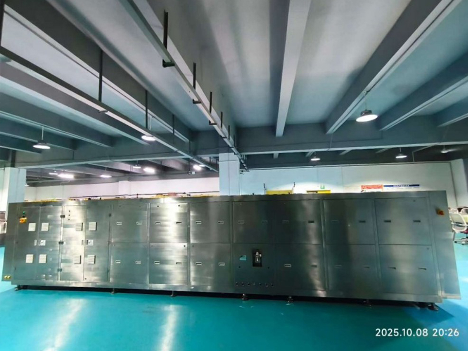
If the data shows the oven cannot meet the profile at the throughput you need, an oven like the JT TRV reflow oven can be assessed against the same tests. The listing describes uniform heating and adjustable temperature profiles, but it does not publish zone counts, tunnel length or conveyor specifications, so request them. Match them to board width, board weight, alloy and the throughput of the upstream stations, using the logic of tunnel length, profile time and conveyor speed.
How Do You Keep Mixed Equipment Connected?
Mixed-brand lines work when the interfaces are planned, not assumed. Two layers matter.
Board handoff. The older electrical convention between machines is SMEMA. Its successor, IPC-HERMES-9852, is specified to replace the SMEMA electrical interface and to carry data such as unique board IDs, barcodes, conveyor speed and board dimensions. Ask each supplier which interface the machine supports and whether a retrofit adapter is available for the older machines in the line. Test handshake timing and signal behavior during commissioning, since two machines that each meet the same interface can still behave differently when paired.
Data exchange. IPC-2591 Connected Factory Exchange is designed for machine-to-machine and machine-to-system communication. In April 2025, IPC released CFX version 2.0, stating that the SDK is backward compatible with earlier versions and that placement reporting was extended to include pick-and-place cycle details. Ask whether a machine natively supports CFX or needs a gateway, because older machines may need one to feed a common data layer.
Add these physical and utility checks to the same review:
- Conveyor height, rail width range, flow direction and lane configuration.
- Power configuration and compressed air pressure, which suppliers typically ask for in a quotation request.
- Floor footprint, maintenance access and any exhaust or nitrogen requirements.
- Software versions and licensing for programming, recipes and data export.
When Does a Phased Approach Stop Making Sense?
A phased plan has limits. Consider a broader line discussion when:
- Three or more consecutive stations are all limiting the production goal, so each phase only moves the constraint a small distance.
- A critical older machine can no longer be serviced or sourced with spare parts at acceptable cost or lead time.
- The product roadmap needs a capability, such as much finer components, that the existing platform cannot support.
- Integration cost and downtime across many partial upgrades approach the cost of a planned replacement.
Treat each phase as a project with its own exit criteria, such as a target first-pass yield or measured line output, and review them before releasing budget for the next one. Phase one should also leave the line in a state that supports phase two, so that no purchase depends on one that has not happened yet.
What Should Buyers Specify Before Requesting a Quote for the Next Phase?
A quotation for one phase is only as accurate as the line information behind it. Prepare these items:
- Existing line inventory: make, model and approximate age of each machine, conveyor specifications and software versions.
- Product mix: board size range, parts per board, smallest component size and any special assemblies.
- Target throughput: a measured current output and the output you need after the phase, expressed in boards per hour as well as placements per hour where relevant.
- Constraint evidence: cycle times and defect data from the diagnostic step.
- Utilities: available power configuration and compressed air pressure.
- Commercial terms: preferred shipping terms, destination, target delivery date and a budget range per phase.
- Data requirements: interface standard, traceability needs and whether an NDA is needed before sharing board files.
The inquiry forms on the supplier’s product pages ask for target throughput, board size, minimum component size, parts per board, power, compressed air, shipping terms, destination, budget range and delivery timing, so assembling this information once speeds up every request. Ask each supplier to state in the quotation what is included, such as installation, training, programming support, interface adapters and spare parts, so that each phase can be compared on the same basis.
Frequently Asked Questions
Can I mix SMT equipment brands in one production line?
Yes, if the machines share a compatible board-handling interface, such as SMEMA or IPC-HERMES-9852, and the conveyor dimensions align. Feeders, nozzles and programs usually do not transfer between brands, so budget for them and test handoff behavior at commissioning.
Which SMT machine should be upgraded first?
Upgrade the station that limits good-board output, based on measured cycle times and defect data. Placement is not always the answer. Printing, inspection or reflow stability often delivers more usable output per dollar when they are the true constraint.
Will a faster pick and place machine increase line output?
Only until the next slowest station becomes the limit. If the printer, oven or inspection station runs slower than the new mounter, line output rises less than the rated speed suggests. Compare real cycle times across every stage before buying.
How do I know whether my reflow oven is the bottleneck?
Compare the oven’s board-to-board interval with upstream cycle times, and run a thermal profile on a representative board. If the profile meets the paste datasheet at the required conveyor speed and the interval is no longer than upstream cycle times, the oven is probably not the constraint.
What interface standards should new SMT equipment support?
Ask about SMEMA compatibility at minimum, IPC-HERMES-9852 for richer board handover data, and IPC-CFX for machine-to-system data. Confirm each in writing, and ask whether adapters are needed for existing machines.
When is it better to replace the whole SMT line?
When several consecutive stations are constraints, critical machines cannot be supported, or the product roadmap exceeds the platform’s capability. At that point, partial upgrades often cost more in integration and downtime than a planned line replacement.