A board can roll out of reflow looking clean enough to impress a sales rep—nice fillets, tidy outlines, polarity marks where they should be, no obvious carnage under the AOI camera—and still be electrically wrong in a way that burns hours in debug because somebody loaded the wrong resistor decade, flipped a diode, or let a rail short sneak past visual inspection. It happens. A lot.
And that’s the scam.
I frankly believe too many factories confuse “nothing looked weird” with “the assembly is verified.” Those are not the same sentence. Not even close. A board doesn’t get a free pass because the placement image looks pretty on a monitor. It has to behave on the nets, on the rails, at the component level, under measurement. That’s where In-Circuit Testing earns its keep, and that’s why I still treat it as one of the few quality gates that cuts through shop-floor optimism.
The bigger manufacturing backdrop matters too, because this isn’t just a nerdy test-engineering argument about fixtures and probe pins. The U.S. Census Bureau’s 2024 semiconductor industry snapshot reported that U.S. semiconductor and related device manufacturing establishments increased from 1,876 in Q1 2020 to 2,545 in Q1 2024, while equipment spending in semiconductor and other electronic component manufacturing rose from $14.4 billion in 2020 to $30.3 billion in 2022. More factories. More CAPEX. More chances to ship an electrical mistake at scale.
Why In-Circuit Testing still matters
But let’s not make this too abstract. In-Circuit Testing is a board-level electrical verification method used to check whether placed components and connected nets actually behave the way the schematic, layout, and BOM say they should before the board gets kicked downstream into functional test, system bring-up, rework, or—worst case—customer-facing failure analysis.
Here’s the ugly truth.
A resistor can be perfectly centered and still be the wrong value. A capacitor can look harmless and still be loaded backward. A lead can wet just enough to satisfy a casual glance and still be unstable under measurement. AOI is useful. Of course it is. But AOI sees appearance. ICT sees behavior. That gap is where money disappears.
And defect behavior is never as tidy as people want it to be. A 2024 Scientific Data paper introducing the DsPCBSD+ PCB defect dataset documented 20,276 annotated defects across 10,259 images in nine categories. That paper was built for machine-vision work, sure, but I read it differently: it’s another reminder that defect modes sprawl. They don’t line up neatly for one inspection station to heroically solve.
What ICT actually verifies
So what are we really checking? Not cosmetics. Not vibes. Electrical consequences.
In practical PCB assembly testing, ICT goes after opens, shorts, missing parts, wrong-value passives, polarity mistakes, continuity faults, rail issues, and selected powered conditions depending on the program and fixture access. When it’s done properly, it also gives you something even more valuable than the pass/fail itself: localization. You stop asking, “Why is the unit dead?” and start asking, “Why is this node wrong?”
That shift matters.
From my experience, once a team gets serious about in-circuit test, all the lazy assumptions start cracking. The “approved alternate” resistor reel that slipped into production. The part library inconsistency nobody fixed because it “only affected one package family.” The diode orientation that looked right to a harried operator under bad lighting. The net everyone assumed was fine because the board looked textbook after reflow. ICT is rude like that. It forces the board to stop posing.
And that’s the point of “electrical verification of placements.” It does không mean the component merely landed in the right coordinates. It means the placed component is the right value, on the right nodes, with the right polarity, and it behaves the way the circuit expects under actual measurement. That’s real process and quality work—not inspection theater.
How in-circuit testing works on a production line
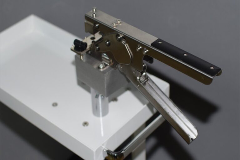
Usually, the machinery is straightforward even if the implementation isn’t: a bed-of-nails fixture—or some variation of a dedicated probing setup—lands spring-loaded pins on defined test pads or accessible nodes, then the tester runs through programmed checks for continuity, resistance, capacitance, isolation, diode response, shorts, and sometimes limited powered tests to decide whether the assembly is electrically sound or hiding a defect behind a very respectable exterior.
It sounds clean. Usually.
Because the ugly part shows up upstream. Test access. Guarding strategy. Probe density. Pad survivability. Layout compromises. The fixture itself is never the whole story. If DFT gets treated like an afterthought, if the layout team prioritizes routing purity over access, if dense double-sided populations and shield cans squeeze out probeable nodes, then the ICT program becomes a half-blind interrogator.
I’ve seen that movie.
That’s why I’d never treat ICT as a late bolt-on after equipment selection is done. It needs to sit inside broader Giải pháp dây chuyền sản xuất SMT trọn gói planning, not get stapled on after placement strategy, reflow profile work, and inspection decisions are already politically locked. And yes, that includes boring stuff—fixture maintenance, pin wear, contamination control, limit tuning, false-call analysis. Boring stuff kills yield.
ICT vs AOI, SPI, and functional test
People keep asking the wrong question. “ICT vs functional test?” No. That’s too binary. Manufacturing doesn’t work like a debate club.
Here’s how I see it: SPI catches print nonsense before the board is loaded, AOI catches visible assembly mistakes, ICT catches electrical lies, and functional test catches product-level behavior under power, firmware, interfaces, and load. Stack them properly and the line gets smarter. Rip one out and the next station inherits the mess.
| Phương pháp | Main purpose | What it catches well | What it misses or handles poorly | Typical line position |
|---|---|---|---|---|
| SPI | Verify solder paste deposit quality | Paste volume, height, offset, area issues | Wrong component values, post-placement electrical faults | After printing |
| Kiểm tra chất lượng bằng máy (AOI) | Inspect visible assembly results | Missing parts, polarity marks, skew, tombstones, visible bridges | Electrical correctness of a visually acceptable board | After placement or reflow |
| ICT / In-Circuit Test | Electrically verify placements and nets | Opens, shorts, wrong values, polarity errors, continuity, rail checks | System-level behavior, inaccessible nodes, firmware issues | After assembly |
| Functional Test | Confirm product behavior in operation | Power-up behavior, interfaces, firmware response, real-world operation | Fast localization of board-level component errors | End-of-line |
I frankly believe AOI gets oversold because it’s photogenic. Screenshots are easy. Electrical truth isn’t. AOI can tell you a component appears present and aligned; it can’t always tell you whether the 4.7 kΩ you needed became a 47 kΩ because somebody fat-fingered a reel change at 2:10 a.m. That’s not a visual problem. That’s an electrical problem.
Functional test, meanwhile, is invaluable—but it’s a lousy place to discover a simple board-level defect you could’ve isolated much earlier. Once a failure reaches end-of-line, you’re not just testing anymore. You’re doing detective work.
Where ICT fits best in modern SMT manufacturing
Yet ICT isn’t equally attractive on every line, and pretending otherwise is just brochure talk. On stable products, repeat builds, decent pad access, and meaningful volumes, the fixture cost is usually justified because cycle time stays short, debug gets sharper, and fault isolation stops eating labor. On chaotic high-mix, low-volume NPI builds, the math gets rougher—fast.
Still, here’s what I’ve learned: “rougher economics” often becomes cover for sloppy discipline. Teams tell themselves they’ll just lean on AOI, flying probe, and end-of-line test until volumes justify a dedicated fixture. Sometimes that works. Sometimes it quietly breeds a rework culture where everyone accepts too much mystery as normal.
Bad habit.
And the cost of electrical escapes in the real world is not theoretical. The NHTSA recall report 24V-915 states that PACCAR recalled 220,972 Peterbilt and Kenworth vehicles in December 2024 because electrical noise and low signal strength could affect Bendix EC80 control units. In another case, Reuters reported in September 2024 that BYD was recalling nearly 97,000 EVs over a steering control unit manufacturing fault that posed fire risk. No, I’m not claiming a missing ICT step caused either case. I’m saying the market is merciless when electrical faults get loose.
That part scales.
Common implementation mistakes and how to avoid them
But most ICT failures I see aren’t failures of the concept. They’re failures of execution. The first mistake is timing—teams wait too long, then realize access is poor and coverage is compromised. The second mistake is over-trusting AOI, as if a clean image settles electrical questions. The third mistake is underestimating line-maintenance reality: bent pins, dirty pads, weak guarding, unstable limits, drifting contact quality, rushed debug loops.
That last one hurts.
From my experience, once a tester starts throwing noisy false calls, the whole station’s credibility erodes. Operators stop trusting it. Engineers start “interpreting” results instead of respecting them. Meetings multiply. Root-cause gets fuzzy. Somebody eventually says ICT itself is unreliable, when the real problem is that nobody maintained the fixture, reviewed the limits, or protected the test access in the first place.
That’s why I’d ask for evidence, not promises. Real Trường hợp khách hàng matter more than polished sales copy, and solid Đào tạo và hỗ trợ sau bán hàng matters more than some inflated coverage number on a slide deck. A tester is only as trustworthy as the people and processes wrapped around it.
Câu hỏi thường gặp
What is In-Circuit Testing in PCB assembly?
In-Circuit Testing is a fixture-based electrical test method that probes a populated PCB to verify component values, polarity, continuity, opens, shorts, and selected net conditions before the board proceeds to higher-level functional evaluation. That makes it one of the most direct ways to confirm that placements are electrically correct, not just visually acceptable.
It’s the board-level truth serum. Harsh, but useful.
How does in-circuit testing work?
In-circuit testing works by contacting defined PCB nodes through a bed-of-nails or similar fixture and then running programmed electrical measurements that check continuity, resistance, capacitance, diode behavior, isolation, and selected powered conditions against known limits. The result is a fast, repeatable pass-fail decision with location-specific diagnostic value.
No access, no confidence. That’s the short version.
What is the difference between ICT and functional testing?
ICT verifies board-level electrical correctness at the component and net level, while functional testing verifies whether the assembled product performs correctly under power, firmware, interfaces, and operating conditions. The two methods are complementary because they detect different classes of failure and do so at different cost points.
I wouldn’t pit them against each other. Different jobs.
Can ICT replace AOI?
ICT cannot replace AOI because it does not provide the same visibility into physical alignment, solder appearance, marking, or certain visual assembly defects, just as AOI cannot replace ICT for direct electrical verification of component values, continuity, and net integrity. The strongest manufacturing flows use both methods in sequence.
One sees shape. One sees electrical behavior. Keep both.
When is bed-of-nails testing the right choice?
Bed-of-nails testing is the right choice when product volume is high enough to justify a custom fixture, the PCB has usable test access, and the business benefits from short cycle times and repeatable board-level fault isolation. Under those conditions, it usually outperforms slower alternatives in throughput and consistency.
If the design changes weekly, maybe not. If the product is stable, probably yes.
If you’re serious about tightening PCB assembly testing instead of just talking about quality in generic terms, start by looking at the full Hệ thống kiểm tra SMT and the wider process and quality chain—then Liên hệ với đội ngũ and work backward from your board access, likely defect modes, fixture strategy, and throughput targets.