Component drop-offs rarely begin as dramatic failures. More often, they start as small, repeatable losses in pickup stability: a nozzle that no longer seals cleanly, a vacuum curve that looks acceptable at idle but weakens under motion, or a recipe that still reflects the previous product mix rather than the package family currently running.
That distinction matters. In most SMT environments, the line does not collapse because one parameter is wildly wrong; it drifts because several related variables move just far enough out of tolerance to create missing parts, rotated placements, sticky releases, and a steady increase in inspection noise. Nozzle suction pressure calibration sits at the center of that drift, which is why it deserves to be treated as a process-control discipline rather than a maintenance afterthought.
Why Component Drop-Offs Are Usually Vacuum Problems
Teams often start in the wrong place. They check feeder consistency, vision alignment, board support, or operator handling because those issues are visible and easy to discuss. Vacuum behavior is less obvious, especially when the machine still appears to be picking most parts successfully.
In practice, the underlying fault is frequently a degraded grip window. The nozzle may be slightly undersized for the package, pickup centering may be off by a small but significant margin, the sealing surface may be worn, or the filter path may be partially contaminated. None of those issues needs to be severe on its own. Together, though, they reduce holding stability during acceleration and transfer, which is exactly where seemingly random component drop-offs begin to show up.
That is why I do not regard missing-part events as isolated mechanical noise. On a modern line, they are usually measurable signs that pickup force, nozzle geometry, and release behavior are no longer working as a matched system.
What Nozzle Suction Pressure Calibration Actually Controls
The term “nozzle suction pressure calibration” is often used too narrowly. It sounds like a single vacuum setting, adjusted once, verified quickly, and then left alone. That interpretation is incomplete.
A reliable calibration process aligns several variables at once: nozzle diameter, vacuum force under load, pickup position, Z-height at pickup, dwell time, transfer stability, and release timing at placement. The goal is not maximum holding force. The goal is a controlled process window in which the component remains secure during motion and then releases cleanly at the intended placement point.
This is where many lines make the same mistake. When parts begin dropping, operators raise suction to compensate. That can help temporarily, but it can also create a second problem: parts that cling too long, shift at placement, or release late enough to create skew and false rejects downstream. Higher vacuum is sometimes necessary. Blindly higher vacuum is not calibration.
The better approach is structured and component-specific. Tiny passives, leaded discretes, QFNs, connectors, and odd-form parts do not behave the same way. Their mass, underside texture, coplanarity, and contact surface all influence how they respond to vacuum and release. A single “good” setting rarely remains stable across all of them.
What Recent Research and Standards Actually Show
The case for tighter control is not theoretical. In the Binghamton University defect-pattern study, researchers examined simulated pick-and-place defects and found that the wrong nozzle size increased placement-offset variability and the probability of component drop during transfer, while pickup-position error affected rotated placement offset. That matters because it ties nozzle selection and pickup accuracy directly to placement stability rather than treating them as secondary setup details.
Standards pressure has moved in the same direction. The ANSI summary of IPC A-610J-2024 notes that the revision was published in March 2024 and remains the dominant acceptance reference for electronic assemblies. For manufacturers building to Class 2 or Class 3 expectations, that means upstream pickup instability is no longer something that can be tolerated simply because downstream inspection may catch the visible failures.
The broader industry trend is also clear. The 2024 National Strategy on Microelectronics Research emphasizes higher-speed inspection and defect reduction closer to the point of manufacture, and the 2024 real-time inspection paper argues for inline monitoring using the pick-and-place process itself. Taken together, these sources point to the same conclusion: pickup stability belongs inside active process control, not at the edge of maintenance documentation.
Where Calibration Breaks Down on the Line
The breakdown is usually gradual, which is one reason it gets misread. A line may continue producing acceptable boards while subtle indicators start accumulating: more rotated parts, a rise in sticky nozzle events, slightly higher AOI noise, occasional touch-up intervention, or more variation after changeovers.
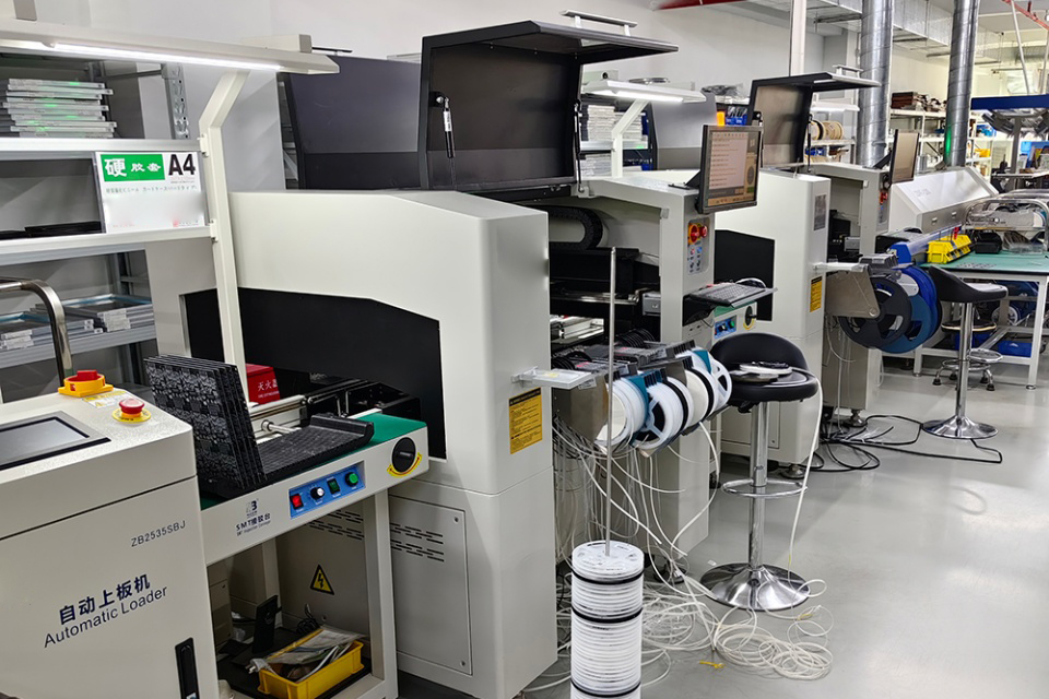
That pattern becomes especially visible in mixed production. A line tuned for stable 0603 work can look healthy until it moves into smaller passives, low-mass ICs, or fine-pitch packages without updating the nozzle family or recalibrating the vacuum-and-release window. The operator may compensate with more suction or lower speed, and the line may appear stable for a short period. Once contamination, head temperature, or cycle demand increases, the weak point reappears.
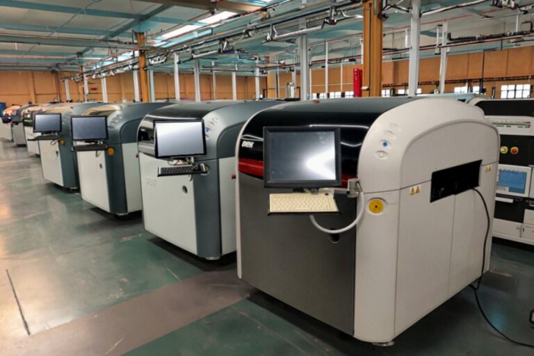
The machine brand changes the interface, not the underlying physics. Yamaha YSM20R, Panasonic NPM-D3, Hanwha SM485, and Juki RS-1R platforms all manage settings differently, but nozzle seal quality, pickup centering, dwell time, and release timing still determine whether the part arrives at the pad consistently.
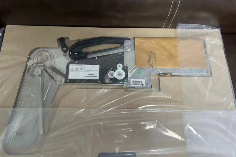
This is also why formal process discipline matters more than reactive troubleshooting. Stronger control over SMT nozzle selection and maintenance, integration with a broader process quality routine, and a disciplined maintenance and spares workflow usually do more to reduce drop-offs than another round of emergency parameter changes.
A Practical Diagnostic Table for Drop-Off Events
When the line starts losing parts, the fastest way to restore control is to diagnose the failure mode before changing multiple settings at once.
| Triệu chứng trên đường dây | Thông thường, điều đó có nghĩa là | Check first | Bad reaction to avoid |
|---|---|---|---|
| Component drops during head travel | Vacuum under load is too low or leaking | Nozzle lip, O-ring, filter, hose, ejector/venturi | Raising vacuum blindly |
| Part picks but rotates | Pickup is off-center or nozzle size is wrong | Pickup X/Y centering, nozzle ID, vision teach | Re-teaching fiducials first |
| Part stays stuck to nozzle at placement | Hold force is too high or release timing is late | Blow-off timing, vacuum decay, nozzle contamination | Slowing the whole line |
| Failures spike after changeover | Wrong nozzle family or stale recipe data | Program-to-nozzle map, feeder/nozzle cross-check | Blaming the feeder only |
| Good yield in the morning, bad yield later | Filter loading, residue, heat drift, seal wear | Vacuum trend by shift, cleaning interval, head temp | Calling it “random variation” |
| Small passives stable, larger ICs unstable | Window was tuned for one package family only | Component-group calibration matrix | One setting for all parts |
The value of this table is not simplicity; it is discipline. Most sustained line losses happen because several variables are changed before the original failure mode has been isolated. Once that happens, the team may improve one symptom while creating another.
Building a Stable Calibration Routine
A stable routine starts with repeatable logging. Nozzle ID, vacuum under load, pickup X/Y deviation, Z-height, release delay, filter age, and failure pattern by component family should be tracked through at least several shifts, especially after changeovers or maintenance work.
It also helps to stop treating knowledge as informal craft. Lines that rely on one experienced technician often perform well until that technician is unavailable or a new product mix exposes undocumented assumptions. Structured Đào tạo và hỗ trợ sau bán hàng reduces that dependency by converting individual experience into repeatable control steps.
The business case is straightforward. Better calibration reduces missing parts, rotated placements, sticky releases, false rejects, rework load, and operator intervention. Just as important, it reduces the chance that a subtle process escape will move farther downstream than it should.
That last point has consequences beyond yield. Reuters reported in March 2024 that the FDA classified Vyaire Medical’s respiratory-device recall as its most serious type; the case involved a manufacturing defect, 37 reported incidents, two injuries, two deaths, and more than 6.6 million recalled devices in the United States. Different product category, certainly, but the process lesson is hard to ignore: once a manufacturing escape reaches the field, the vocabulary shifts from efficiency to liability. (reuters.com)
Câu hỏi thường gặp
What is nozzle suction pressure calibration? Nozzle suction pressure calibration is the process of matching vacuum force, pickup timing, nozzle geometry, and release behavior to a specific component so the pick-and-place head can transport it without dropping, rotating, sticking, or releasing late. In practical terms, it means controlling the entire pickup-and-release window rather than adjusting one vacuum value in isolation.
What causes component drop-offs in SMT? SMT component drop-offs are usually caused by an unstable pickup-and-transfer condition created by wrong nozzle size, vacuum leakage, poor pickup centering, worn seals, dirty nozzles, clogged filters, incorrect Z-height, or release timing that no longer matches the current component package. The reason the defect feels random is that several of those conditions can degrade at the same time.
What is the best suction pressure setting for pick and place machines? The best suction pressure setting is the lowest stable vacuum level that holds the component securely through pickup, transport, and alignment while still allowing clean release at the placement point for that nozzle family, package type, and machine head configuration. There is no single universal value that works equally well for all component classes.
How often should SMT nozzle calibration be checked? SMT nozzle calibration should be checked at every changeover, after nozzle replacement, after head maintenance, and whenever AOI or placement data shows new missing parts, skew, rotation, or sticky release behavior. Waiting until visible failure appears usually means the process has already drifted for longer than the team realizes.
Can nozzle vacuum calibration reduce false rejects and rework? Nozzle vacuum calibration reduces false rejects and rework by stabilizing pickup, transfer, and release before the board reaches downstream inspection, which lowers the incidence of missing parts, borderline placements, and sticky nozzle events that consume technician time even when they do not become formal scrap. It is one of the clearest examples of upstream process control reducing downstream noise.
If your line is showing new drop-off behavior, the next step should be diagnostic rather than speculative. Track the key variables, compare performance by component family, and isolate the real failure mode before changing multiple settings at once. For machine-specific guidance, use the Trang liên hệ and treat nozzle suction pressure calibration as the yield-control lever it actually is.