If you’ve ever built boards with fine-pitch QFPs or BGAs, you already know the pain: everything looks “ok” on top, but the real drama hides under the package. A tiny placement mistake can turn into bridging, head-in-pillow, or weird opens that show up way later in test.
Here’s my stance: high-precision nozzles aren’t just accessories. They’re a process control tool. When pitch gets tight, your nozzle design and placement force control start deciding your yield.
Fine-pitch placement and solder paste bridging
Placement force and solder paste squeeze-out
Fine-pitch isn’t forgiving. If you hit the paste too hard, the paste can squash and spread. That’s how you get bridging and shorts—sometimes under parts where AOI can’t see. Fuji straight up calls out that higher load during fine-pitch placement can spread solder paste and cause bridging, plus the ugly extras like solder balls.
Infineon says the same thing from the BGA side: you need enough placement force, but not excessive, because too much force can squeeze paste out and create solder joint shorts.
So yeah… “just push it down harder” is not a plan.
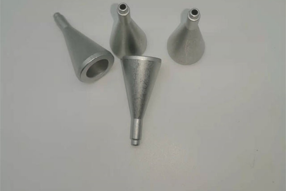
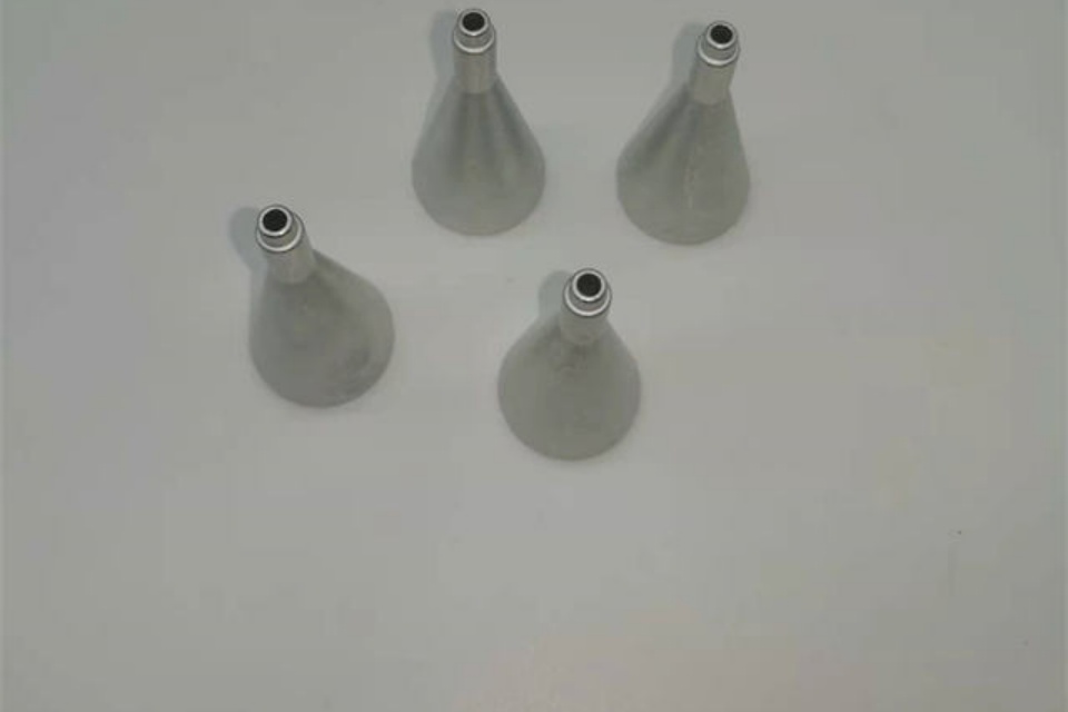
Low impact nozzle design
Two-piece nozzle shock absorption
One practical way to protect paste (and fragile parts) is to absorb impact at the nozzle, not by slowing the whole machine down.
Fuji describes a two-piece nozzle design that absorbs placement shock, reducing load without needing to reduce placement speed. They even state low-impact placement down to 0.5 N at top speed, aimed at preventing damage and solder bridging without killing productivity.
That’s the core argument:
Don’t trade speed for gentleness if the nozzle can do the cushioning.
Panel height detection and warpage compensation
Here’s the sneaky part: you can have a perfect nozzle and still crash parts if the PCB is warped.
Fuji highlights measuring panel warpage and offsetting placement height so the correct load gets applied whether the panel bows up or down.
On the shop floor, this matters a lot for thin panels, high copper imbalance, slots, and dense layouts. You can clamp all day and still lose.
Z-axis resolution and mount force control
Z-axis resolution of two micrometers
When you chase fine-pitch and tiny passives, Z control becomes your “feel”. If Z steps are rough, your placement force control is basically guessing.
Mycronic’s solution brochure states the Midas mounthead has z-axis resolution of two micrometers, tied to sensors so delicate parts get the correct mount force.
Intelligent Surface Impact Control and warped boards
That same brochure explains how the z-axis servo system prevents both high-impact force and insufficient mounting pressure, even on warped boards, and helps avoid microcracks on sensitive components.
In real production language: you stop seeing random “mystery cracks” that pop after reflow or after thermal cycling.
BGA component placement and centering
Ball recognition instead of outline recognition
BGAs love to trick vision systems. The package outline isn’t always perfectly aligned to the solder balls.
Infineon recommends using ball recognition rather than outline recognition for centering, because it removes tolerance between the ball and the package body.
That’s a big deal when your solder balls are your real electrical interface.
Manual placement is asking for rework
Infineon also warns against manual positioning, especially for small terminations and pitch, because accurate placement matters even with self-alignment during reflow.
So if your line still “hand nudges” BGAs under a microscope… you’re basically scheduling rework for Friday night.
Solder paste printing and fine pitch BGA reality
Stencil thickness 100–150 μm
Nozzle control can’t fix bad paste deposits. You need paste volume that matches micro-pitch.
Infineon notes stencil thickness for BGA can vary between 100 and 150 μm, depending on area ratio, material, and aperture diameter, with circular apertures for BGA.
0.3 mm pitch case with lower rework and zero tombstoning
There’s also a strong real-world signal that as pitch drops, process control becomes the only way out.
A Mycronic customer case discusses BGAs/LGAs down to 0.3 mm pitch, reporting 30% fewer boards requiring rework and zero tombstoning (linked to adding a gluing step in the same pass), and yield moving from 80% to around 90%.
Different topic (jet printing / adhesives), same lesson: tight pitch punishes sloppy control.
Argument map with evidence
| Practical argument (what you can defend on the line) | What it changes in production | Evidence source |
|---|---|---|
| High placement load can cause solder paste bridging in fine-pitch | Less hidden shorts under parts, fewer “AOI didn’t catch it” escapes | Fuji warns about paste squash/bridging under fine-pitch. |
| Shock-absorbing nozzle design reduces impact without slowing cycle time | Keeps UPH while lowering mechanical stress and paste spread | Fuji describes two-piece low-impact nozzle, as low as 0.5 N at top speed. |
| Warpage measurement + height offset stabilizes placement load | Fewer nozzle crashes / uneven seating on bowed panels | Fuji panel height detection and warpage-based offset. |
| Fine control of Z-axis improves mount force control | Protects delicate parts, reduces microcracks | Mycronic states z-axis resolution of two micrometers and force control concept. |
| BGA centering should use ball recognition | Better alignment where it actually matters | Infineon recommends ball recognition for centering. |
| Excessive placement force can squeeze paste and short joints | Stops “paste pumping” and shorts under BGAs | Infineon warns about too much placement force causing shorts. |
| Micro-pitch (0.3 mm) needs tighter control to cut rework | Better yield, less rework churn | Mycronic case: 0.3 mm pitch, 30% fewer rework boards, yield ~80→~90. |
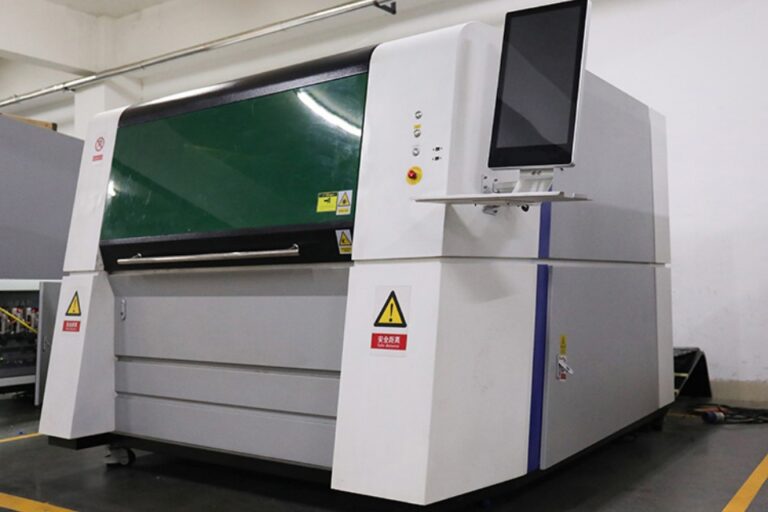
Selective Wave Solder Machine Nozzle
Precise solder flow for mixed-technology boards
Here’s where people forget the bigger picture. Many boards are mixed tech: fine-pitch SMT + through-hole connectors. You might place a BGA on the top side, then later do selective wave on the bottom side.
On Meraif’s site, the Selective Wave Solder Machine Nozzle category is positioned around precise solder flow and durability, improving THT soldering accuracy, efficiency, and assembly reliability.
That fits this whole argument: precision nozzles don’t stop at pick-and-place. If you push solder exactly where it should go (and nowhere else), you reduce bridging risk, heat stress, and rework loops—especially when the board is packed.
Turnkey SMT line decisions that don’t break your yield
Spares, OEM/ODM, and “don’t let the line stop”
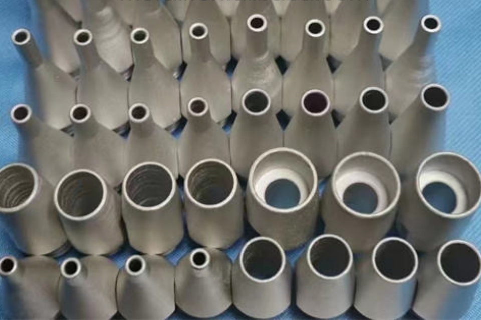
In real factories, the biggest “enemy” isn’t theory. It’s downtime, nozzle wear, vacuum leaks, and random pickup loss.
Meraif positions itself as a turnkey SMT line provider with 20+ years of SMT factory operations experience, covering equipment selection, line design, installation, calibration, commissioning, and support.
The site also emphasizes stocking spares like nozzles and accessories, plus brand coverage and end-to-end line support.
If you’re buying in bulk or doing OEM/ODM, this matters because:
- you want nozzle consistency across lots (same geometry, same vacuum behavior),
- you want fast replacement so changeovers don’t become a mini crisis,
- and you want someone who understands the whole line, not just one part.
Not every supplier talk like this, but it’s what line owners actually ask me about.
Bottom line
When you build fine-pitch and BGA assemblies, you’re not “just placing parts.” You’re managing forces, warpage, paste behavior, and alignment—at speed.
So the smarter argument is simple:
- Use nozzle designs that control impact, not just suction.
- Control Z and warpage, or your load will drift.
- Center BGAs by solder balls, not vibes.
- And don’t ignore downstream soldering—Selective Wave Solder Machine Nozzle choices can protect dense layouts too.