You know the pain: the board passes test, ships, then comes back with an intermittent fail that disappears the moment you touch the probe. That “ghost open” is often a cold solder joint. And no, it’s not just a hand-soldering problem. It shows up in reflow lines too—especially when profiles drift, paste volume swings, or parts move during solidification.
My take is simple: cold solder joints aren’t random. If you stack the right detection methods and run root cause analysis like a process engineer (not like a firefighter), you can kill most of them for good.
Cold solder joint definition and visual clues
A cold solder joint typically forms when heat is insufficient or part of the joint never reaches soldering temperature. One common clue is an abrupt line of demarcation instead of a smooth fillet. And here’s the trap: it can look shiny or dull, so “dull = bad” isn’t reliable by itself.
In real production, you’ll usually see cold joints show up as:
- intermittent opens (tap the board, it wakes up, then dies again)
- high resistance that makes signals noisy
- failures after vibration or thermal cycling (field returns love this one)
Cold solder joint detection methods in production
Cold joints hide in plain sight. So don’t bet everything on one inspection gate. Use a layered approach.
Visual inspection and AOI
Visual checks (or AOI) can catch obvious issues: rough texture, odd fillets, gaps, disturbed joints. But lead-free joints can look matte even when OK, so you still need functional signals to back it up.
Continuity and resistance checks
For “it fails only sometimes” boards, basic continuity isn’t enough. You want:
- resistance checks (watch for unstable readings)
- gentle mechanical stress (wiggle test, light flex—controlled, not savage)
This matches what high-reliability workflows do: continuity checks plus inspection results to confirm the joint integrity.
X-ray inspection for hidden joints (BGA, QFN)
If the solder joint is hidden, you can’t visually inspect it in any normal way. That’s why X-ray shows up in serious reliability programs—especially for BGAs and other area array packages.
High-reliability standards get very specific here:
- X-ray equipment should use micro-focus and high-resolution detection
- some requirements reference detecting very small solder-ball features (down to 0.03 mm) and controlling component dose during inspection
- AXI can run inline, but it doesn’t replace final visual inspection
Microsection analysis and metallographic cross-section
When you need the “why,” not just the “what,” microsection (cross-section) analysis becomes your truth serum. It can reveal internal cracks, voids, and weak intermetallic development that you simply won’t see from the surface.
Yes, it’s destructive. But if you’re stuck with repeat RMAs and NFF (no-fault-found) drama, destructive beats clueless.
Detection methods cheat sheet (shop-floor friendly)
| Detection method | Best at catching | Often misses | When you should use it | Source type |
|---|---|---|---|---|
| Visual inspection / AOI | obvious fillet issues, disturbed joints, missing/wrong polarity | hidden joints, internal cracks, borderline wetting | first-pass screening, quick line checks | workmanship guidance |
| Continuity / resistance | intermittent opens, high resistance paths | internal structure detail, early-stage microcracks | debug “fails only sometimes” boards | reliability practice |
| X-ray inspection (2D/AXI) | shorts/bridges, void patterns, hidden joint anomalies | some opens can be hard, metallurgy detail | BGA/QFN/LGA, hidden interconnects | NASA/ECSS guidance |
| Microsection analysis | cracks, voids, intermetallic quality | non-representative if sampling is poor | root cause confirmation, FA lab work | metallography practice |
Sources supporting the table: ECSS cold-joint definition , NASA guidance on X-ray + continuity checks , ECSS X-ray equipment requirements , microsection/metallography use .
Root cause analysis: heat, surface condition, motion, and solder volume
If you want fast RCA, bucket the causes. Don’t chase 30 theories at once.
Reflow profile and insufficient heat
Not enough heat is a classic cause: solder doesn’t fully melt, wet, and form a strong bond. In production, this often comes from:
- profile drift (zone temps, conveyor speed)
- high thermal mass areas that sink heat
- lead-free process windows that are tighter (needs higher/steadier heat)
This “not enough heat” pattern shows up repeatedly in practical guidance.
What to do: lock profile control with a thermal profiler, and don’t trust the oven display. Measure the board at the joint locations that actually fail. Profiling isnt glamorous, but it ends arguments fast.
Oxidation, contamination, and flux activity
Dirty or oxidized pads/leads block wetting. Even good heat won’t save you if the surface chemistry is wrong. Practical guides call out “dirty/oxidized surfaces” as a direct cause.
What to do: tighten incoming material control, storage, handling, cleaning strategy, and flux management. This is where ESD control and clean handling habits matter more than people admit.
Movement, vibration, and disturbed solder joints
A joint can look “almost fine” but fail because the part moved while the solder was freezing. Standards for soldering equipment explicitly warn about movement or vibration causing misalignment or disturbed solder joints.
What to do: check conveyors, board supports, clamps, and any upstream mechanical shock. Also check placement force/bounce. If your mounter is slamming tiny passives, you’re basically rolling dice.
Solder paste volume variability and placement accuracy
Paste volume swings create borderline joints. NASA’s BGA work shows real failures tied to small solder deposits and also points out defects possibly due to variability in solder paste volumes—caught via X-ray and continuity checks.
What to do: treat SPI + stencil health + print setup as first-class controls. And verify placement accuracy when defects cluster around specific packages.
Root cause → evidence → fix (fast RCA table)
| Root cause bucket | Common evidence | Best confirmation tool | What to adjust (typical) |
|---|---|---|---|
| Insufficient heat / bad profile | dull/odd fillets, intermittent opens after thermal stress | profiler + targeted X-ray | reflow profile, preheat/soak balance, zone stability |
| Oxidation / contamination | solder “beads up,” weak wetting, inconsistent joints across lots | microsection + surface review | storage, handling, cleaning, flux selection/control |
| Motion / vibration | disturbed fillets, misalignment patterns, failures after conveyor events | line audit + microsection | conveyors/support, placement force, vibration sources |
| Paste volume variability | opens/weak joints on dense footprints, lot-to-lot swings | SPI + X-ray | stencil/aperture, print parameters, paste management |
Evidence backing: ECSS vibration/movement caution , NASA on deposit-related failures and X-ray/continuity workflow , microsection value .
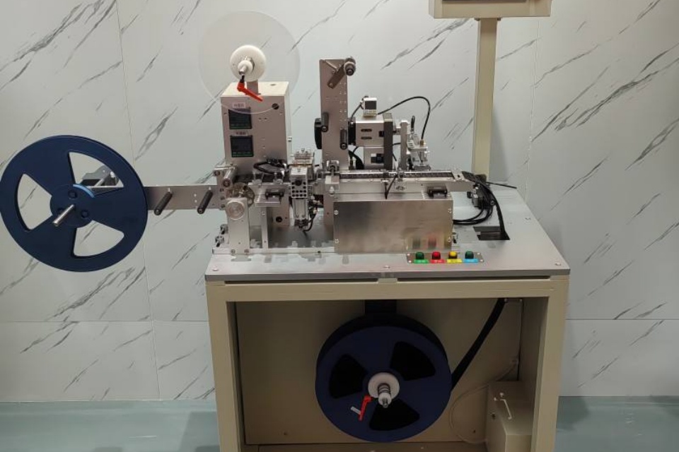
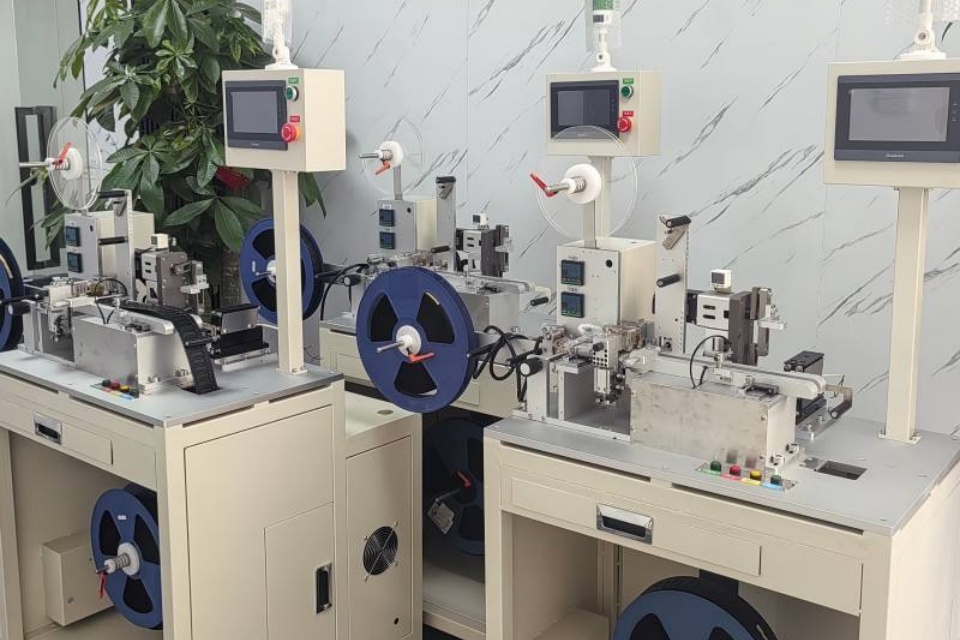
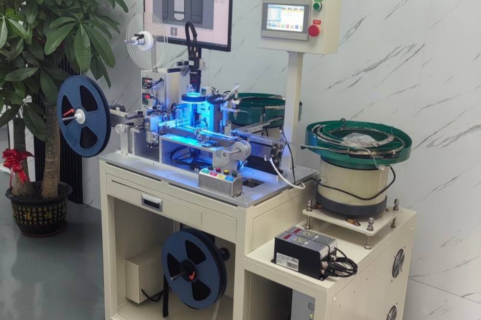
SMD taping machines and reliability control
People think taping is “just packaging.” In reality, it’s part of process control—especially when your customers buy in bulk, run mixed lines, and can’t afford feeder chaos.
Your SMD taping category calls out the real goal: accurate, fast, reliable tape-and-reel preparation for SMT production.
Tape-and-reel quality and feeder stability
Bad pockets, poor pitch consistency, weak cover tape sealing—these create:
- mis-picks
- skewed placement
- nozzle slip
- random micro-shifts that mess with paste contact
Then you end up blaming reflow for a placement problem. Happens all the time, honestly.
Packaging, labeling, and MSL control
Your site also highlights that SMD taping and reeling should support consistent sealing and labeling for safe logistics and MSL control.
That matters because moisture + oxidation risk doesn’t stop at the factory door. If your customer opens a questionable reel, runs it late, and stores it badly, you’ll see wetting problems and weak joints show up downstream.
If you want to point customers to the category without dumping extra distractions, keep it simple:https://pickandplacemachine.com/smd-taping-machines/
Turning detection into a repeatable line playbook
Here’s a practical loop you can run without making the team hate you:
- Contain: quarantine the lot, mark suspect positions, don’t keep producing “maybe-good” boards.
- Triage: visual/AOI + quick resistance checks (look for flicker readings).
- See hidden joints: X-ray the package types you can’t see (BGA/QFN/LGA).
- Confirm the mechanism: microsection 1–3 samples from the worst offenders.
- Close the loop: profile verification + print volume control + motion audit.
Do this and you’ll stop “arguing by feeling.” Your yield will thank you.
Where Meraif fits (without the hard sell)
Meraif positions itself as a turnkey SMT line solutions provider with 20+ years of SMT factory experience, covering consultation, line layout, installation, calibration, and training.
That matters for cold joints because these defects rarely have a single cause. They’re a system problem: printing, placement, reflow, inspection, handling, storage, and packaging all push the outcome.
If you’re a wholesaler or you’re doing OEM/ODM batches, you don’t just need a machine. You need a line that stays stable when the schedule gets ugly and the product mix changes weekly. That’s where a turnkey SMT line solutions mindset helps—less “random tuning,” more controlled process.
Final point
Cold solder joints feel random only when your detection is shallow and your RCA is improvisation. Stack the right inspections, verify the profile, control motion, and treat material handling (including taping) as part of quality—not an afterthought.
You’ll still get defects sometimes. But you won’t be stuck guessing, and thats a big deal.
Appendix: Real-world failure signatures (what your FA team actually sees)
You can use these like a quick “symptom → suspect” map when the line is yelling and the customer wants answers yesterday.
- “NFF” returns with random resets
Usually points to marginal interconnect, not firmware. Cold joints can pass ICT once, then fail after shipping vibration. If your failure rate spikes after logistics, look hard at disturbed joints and weak wetting. - Fails cluster around one package type (BGA/QFN)
This is a big hint. If you can’t see the joint, you can’t eyeball your way out. Do X-ray triage early, then microsection 1–3 parts to stop the guessing loop. - One board edge fails more than the other
Often a thermal gradient story: board support, conveyor rail contact, shadowing, or copper density. Don’t argue—profile it at the failing corner with a thermal profiler. If the numbers don’t match, the joints won’t either. - “Tap test” brings the board back to life
That’s basically a signature of intermittent contact. Add resistance checks under light flex (controlled). If readings jump, stop chasing software.
Appendix: Fast RCA questions (no fluff, just shop-floor useful)
When you’re in a meeting and someone says “It’s the oven,” ask these. They cut through noise.
- Did we change anything?
Paste lot, stencil, nozzle set, feeder bank, conveyor speed, AOI program, oven recipe, operator shift—any of those can move the needle. - Is it a process window problem or a one-off?
If it’s random across the panel, look at paste volume and placement hit rate. If it repeats at the same location, look at thermal map or mechanical support. - Can we reproduce it with stress?
Thermal cycle or light vibration can make marginal joints show themselves. If it only fails after stress, that leans toward weak interconnect, not a “test glitch.” - What does the inspection stack say together?
AOI alone lies sometimes. X-ray alone misses some opens. Electrical alone doesn’t explain why. Stack them, then do microsection when you need proof.
Appendix: Practical controls that reduce cold joints in bulk/OEM runs
If you sell to wholesalers, OEM/ODM, or high-mix factories, you’ll see the same pain points: line stops, yield dips, and “why did this lot behave different” emails.
Here are controls that tend to pay off without turning the line into a science project:
- Profile lock + golden board
Keep a golden board with thermocouple attach points, and re-verify when you swap product families or copper density changes. Profile drift is sneaky. - SPI discipline (paste is the first domino)
If paste volume is unstable, everything downstream becomes RNG. Tighten print setup and keep stencil health under control. - Placement stability (mounter behavior matters)
Excess placement force, bounce, or feeder inconsistency can disturb paste contact. This becomes “cold joint” later, even though the real issue started earlier. - Taping and reeling consistency for stable feeding
If reels are messy, feeders mis-pick, parts skew, and placement gets sloppy. That’s why SMD taping machines matter in the reliability story, not just the logistics story. - Hidden joint strategy
If you build BGA/QFN products, plan X-ray capacity. Don’t treat it like an emergency tool only. It saves days of “maybe” rework.