You can run a fast SMT line and still get crushed by one “small” spec: the work area and the component size limits. It’s not just datasheet talk. These limits decide if your board fits, if parts collide, and if you end up doing awkward hand-insert ops that wreck takt time.
Below is a practical way to think about it, with numbers, shop-floor scenarios, and what to do before you commit to a machine or a full turnkey line.
Pick and Place Machine Work Area
Work area is the machine’s reachable XY envelope (plus what the conveyor/clamps can actually hold). If your PCB/panel doesn’t sit stable inside that envelope, your placement program might be “correct”… and still fail in real life.
Work Area vs Conveyor Reality
Even if a spec says “max PCB size,” you still have to ask:
- Can the rails clamp it without flexing?
- Do edge parts hit clamps or safety cover?
- Do you have edge clearance for fiducials + tooling?
Panelization guides often call out that you should match panel size to your line capability and keep edge clearance for tooling/rails.
PCB Size and Panel Size
If you do high-mix, you already know this pain: one board is tiny, the next is long, then you get a weird panel with connectors hanging off the edge. That’s where “work area” turns into a daily constraint.
Panel Size for Pick-and-Place Efficiency
A bigger panel usually means fewer load/unload cycles and less operator touch time. One panelization example shows a 400 mm × 300 mm working area as a reference point for building panels that reduce changeovers.
But bigger isn’t always better:
- Oversized panels can warp more during reflow.
- Some boards need support pins or a carrier.
- If you don’t control edge clearance, you’ll get clamp interference and random placement shifts.
Component Size Limits
“Component size limits” is really three limits hiding in one phrase:
- Smallest component you can reliably pick
- Largest component you can see + align
- Largest component you can physically place without collision
Component Size Range Examples
On your site, the FUJI NXT-II listing shows component size 0201 to 50 mm × 50 mm and board size 50 mm × 50 mm to 510 mm × 460 mm.
That’s the kind of range you want if you’re doing mixed product (chips + ICs + some larger parts).
Component Height Limit
This is the one that surprises buyers. People obsess over speed (CPH) and forget Z-axis clearance.
Typical SMT Placement Height
One DFM note points out that pick-and-place height limits vary, but average limitation is around 15–25 mm, driven by head travel and physical constraints like safety glass.
Tall Connectors and “Manual Insertion Tax”
FUJI’s own technical content says standard placement machines handle ~25 mm height, and tall connectors often exceed 30 mm, so they get pushed to manual insertion. They also mention a solution supporting up to 38.1 mm (1.5 inches) height to expand what can be automated.
Real shop-floor moment:
You build a line for “mostly SMT.” Then one product uses a tall connector. Now you need a side bench for hand insert, extra QC checks, and your flow becomes… not smooth. It’s a quiet throughput killer.
Vision System and Camera Limits
Vision is not one thing. It’s usually:
- Down-looking camera (fiducials + many standard parts)
- Up-looking/bottom vision (large / fine-pitch / tricky packages)
- Optional diagonal/split vision for oversized parts
A Manncorp MC-series datasheet shows a clear example:
- Head-mounted vision handles components up to 16 mm × 14 mm
- Up-looking options go to 38 mm × 38 mm or 50 mm × 50 mm
- Diagonal vision can inspect up to 150 mm × 100 mm (option)
That’s why two machines can both claim “supports large components,” but one will struggle unless you buy the right camera package.
Quick Limit Cheat Sheet (With Sources)
| Limit keyword | What it controls on the line | Typical value / example | Why you should care | Source |
|---|---|---|---|---|
| Working area / panel fit | XY travel + clampable area | Example: 400×300 mm panel target | Bad fit = handling errors + slower changeover | |
| Board size | Max PCB/panel that conveyors support | FUJI NXT-II: 50×50 to 510×460 mm | Defines if long boards need carriers | |
| Smallest component | Feeder + nozzle + vision stability | FUJI NXT-II: down to 0201 | If you do 0201/01005, setup discipline matters a lot | |
| Largest component (vision) | Whether cameras can align big parts | Up-looking: 50×50 mm; optional 150×100 mm inspection | Big parts without correct vision = rejects | |
| Component height (Z) | Collision risk + whether parts must be hand placed | Avg 15–25 mm; some solutions to 38.1 mm | Tall connectors can break automation flow |
SMT Consumables (Yes, They Affect Your Limits)
People treat consumables like “small stuff.” In real production, they protect your uptime.
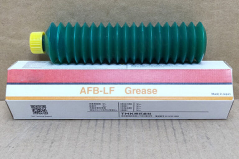
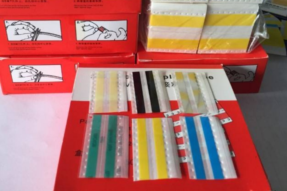
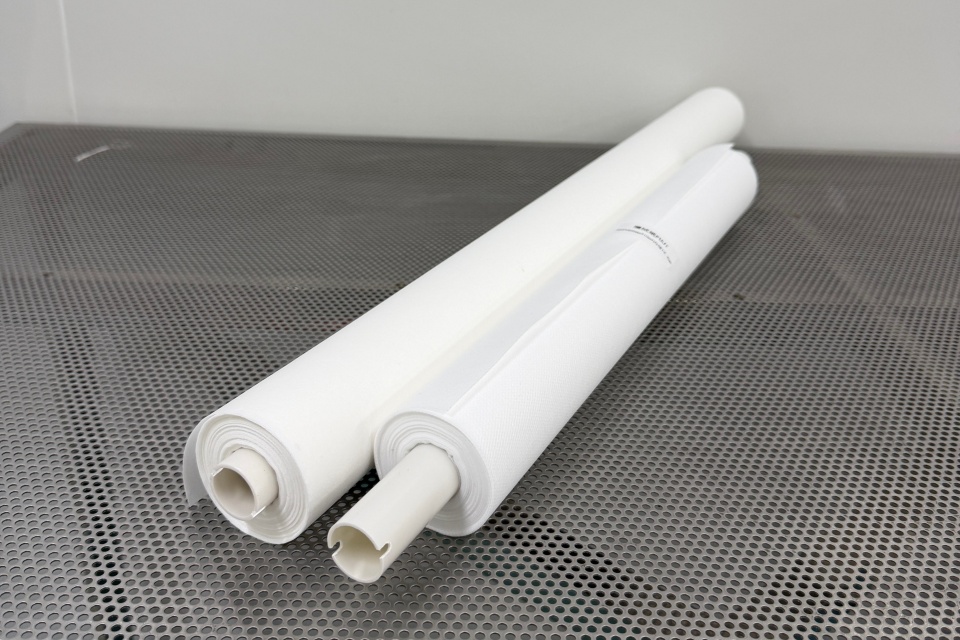
Your SMT Consumables category highlights essentials like tapes, splicing, cleaners, ESD, and maintenance parts to keep production stable.
That’s not marketing fluff—this is literally what keeps your feeders running and your OEE from sliding.
Where consumables hit the limits (real examples)
- Splice tape + splice tools: bad splices = feeder mis-pick spikes right when the line is hot.
- Clean room wipers / stencil rolls: dirty print = paste variation = tombstoning and rework.
- ESD control: static can mess with small passives and tape feed (annoying, unpredictable).
If you want one internal place to start, link your content to SMT Consumables:
SMT Consumables
Real Production Scenarios
Scenario 1: “The board fits… but the panel doesn’t run smooth”
You load a panel that technically fits the conveyor. But the edge clearance is tight. Clamps bite near components. You start seeing random placement offsets near the rails.
Fix: redesign panel rails, keep edge clearance, add proper fiducials, and stop squeezing components to the edge. (Yeah, it’s boring. It saves you weeks.)
Scenario 2: Tall connector forces a manual station
Everything is SMT until that 32 mm tall connector shows up. Now you have:
- a manual insert step
- extra inspection
- uneven WIP piles
Fix: spec for Z-height early. If you can’t, redesign BOM (shorter connector, alternate mechanical), or plan a clean manual cell with fixtures so it dont destroy your flow.
Scenario 3: Big QFN/BGA aligns poorly
Your machine “supports” the package, but the camera setup is wrong. You get rotated placements or skew because the vision system can’t inspect it well.
Fix: confirm bottom vision capability and the actual max component size under that vision mode.
Meraif (Turnkey SMT Line Solutions, Not Just One Machine)
Your homepage positions Meraif as “Top 1 Turnkey SMT Line Solutions Expert in China” with 20+ years of hands-on SMT factory operations, covering consultation, line design, integration, training, calibration, and commissioning.
That matters here because “work area + component limits” is not a single-machine question. It’s a line balance question:
- printer ↔ placement ↔ reflow ↔ AOI/SPI ↔ handling
- feeder count vs changeover time
- product mix vs takt time (high-mix pain is real)
And yeah, if you buy in bulk, need OEM/ODM, or want one vendor that can supply machines + feeders + nozzles + SMT consumables + support, that’s exactly the lane Meraif is already in.
What You Should Check Before You Buy
If you only remember five questions, make it these:
- Max PCB/panel size + real clamp clearance (not just a brochure number)
- Smallest component you’ll run in volume (0201 is not “free”)
- Largest component your vision can actually align
- Max component height you must automate (connectors will sneak up on you)
- Feeder + nozzle + consumables plan (downtime often starts here)