Specs don’t build boards. Control loops do.
If you’ve ever watched an SMT line and thought “it’s just a robot moving fast,” you’re missing the part that decides whether you ship good product or scrap. A modern pick and place machine is basically a coordinated math engine: it converts CAD coordinates into machine coordinates, corrects drift with vision, validates picks with vacuum feedback, and keeps repeating that loop thousands of times per hour while the line quietly tries to sabotage it with tape friction, warped PCBs, worn nozzles, and bad library data.
So what’s the real operating cycle? And where do the seconds actually go?
The pick and place machine working principle is boring on purpose
A pick and place machine working principle, in plain terms, is “measure → decide → move → verify → repeat.” The sexy parts (high speed heads, linear motors, fancy cameras) matter. But the real magic is the boring stuff: coordinate transforms, calibration, thresholds, and error handling.
Here’s the hard truth I don’t see in vendor brochures: most placement problems are not “the machine can’t hit the pads.” They’re upstream data and downstream discipline problems—component packaging variation, feeder setup habits, nozzle selection, and whether your team treats the vision library like a living thing or a one-time checkbox.
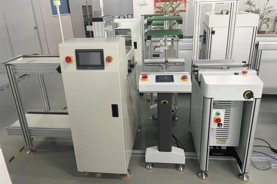
Complete pick and place machine workflow: the operating cycle you can actually audit
I’ll lay out the “complete pick and place machine workflow” the way a line engineer audits it—step-by-step, with the ugly parts included.
1) Program import and library mapping (where failures are born)
Centroid file in. Gerbers in. Package library applied.
If your package definition is wrong (body size, lead span, pickup point, rotation), the machine will still place parts. It’ll just place them wrong at scale. That’s how you get “mystery defects” that show up as AOI noise or reflow defects later.
And yes, this is still part of the operating cycle, because the machine will keep paying for this mistake every single cycle.
2) Feeder indexing and component presentation
Feeders advance the tape. The pocket presents the component at a pickup location.
This looks simple until you measure it. Tape drag, cover tape peel angle, pocket tolerances, and splice quality all change how consistently a component sits when the nozzle comes down. You want stable presentation. You rarely get perfect presentation.
This is why feeder quality and maintenance aren’t “nice to have.” They’re cycle time and yield.
3) Pick: nozzle down, vacuum on, pickup verification
The head moves to the pickup point. Z-axis down. Vacuum engages. Z up.
Then comes the part most people forget: pick verification. The controller watches vacuum pressure (and sometimes flow) to confirm “part attached.” A weak seal or cracked nozzle can pass sometimes and fail other times, which is the worst kind of failure because it destroys trust in your alarms.
Short sentence: mispicks happen.
4) Vision: pre-align, center-of-gravity correction, rotation
Now the machine checks what it actually picked.
For many parts, the camera captures an image and computes offsets: X/Y shift, theta rotation, sometimes even skew. If you run “on-the-fly” vision, this happens while the head is moving, which saves time but increases sensitivity to lighting drift and camera calibration.
Want an uncomfortable question? How often do you re-validate your vision thresholds after you change reels or suppliers?
5) Board entry, clamping, and fiducial acquisition (the real coordinate reset)
The PCB enters on a conveyor. It clamps or supports. The machine finds fiducials.
Fiducials are not “nice.” They are the machine’s anchor points. The controller uses them to calculate board offset and rotation so the CAD placement coordinates match the physical PCB sitting in the machine right now.
This is where your “how does a pick and place machine work” question becomes pure geometry. Without fiducials (or with bad fiducials), you’re placing blind.
6) Place: motion profile, Z control, placement force, and settle time
Head moves over the placement coordinate. Z down. Part placed. Z up.
But there’s a lot hiding inside “place.” The machine must control placement height, contact, and release timing so the part stays on the paste and doesn’t shift. If you push too hard, you smear paste or tilt parts. Too light, and parts can stick to the nozzle and “drop later,” which is chaos.
And yes—settle time is real. The head needs a tiny pause to stop vibration from turning into placement error at high speed.
7) Post-place checks and exception handling (where your throughput disappears)
If the machine thinks something went wrong, it doesn’t just shrug. It does something:
- Retry pick
- Send part to reject bin
- Pause for operator
- Mark placement as “suspect”
- Trigger a stop if error rate spikes
Every exception adds time. And exceptions cluster. One bad reel can drag an entire shift.
8) Repeat: optimize head path, minimize travel, balance feeders
This is the SMT pick and place process at scale: the controller optimizes travel paths and tries to keep the head doing useful work instead of commuting across the table.
But feeder layout still dominates. Put high-usage parts far apart and you just forced longer travel forever. Put odd-form parts in the “wrong” zone and you’ll pay in slower vision cycles.
9) Board exit to downstream process (reflow, AOI, SPI)
The board leaves. The next board enters. The cycle restarts.
Here’s where I get opinionated: if you don’t design the line and only “buy a machine,” you’ll keep blaming the placer for problems caused by printer setup, stencil cleanliness, paste condition, and conveyor handoffs.
If you’re planning a full line, read how turnkey lines are usually scoped, not just sold. The “turnkey SMT line solutions” approach tends to expose bottlenecks earlier, especially around feeder strategy and inspection integration. (Pick and Place Machine)
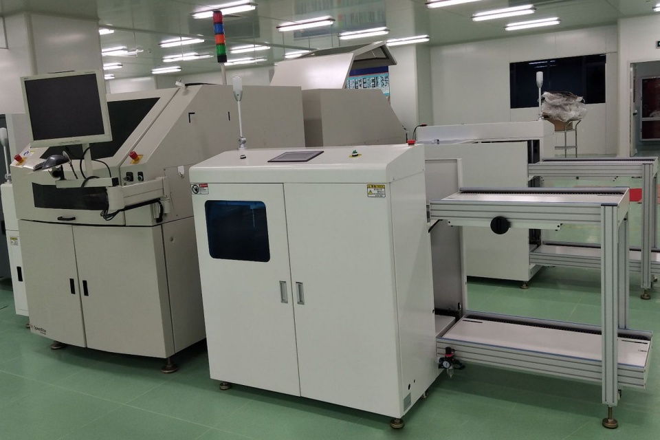
Pick and place machine cycle time: the math people avoid
Cycle time is not the same as “maximum CPH” (components per hour). Specs are typically measured under ideal conditions: small components, optimized layout, minimal vision overhead, no feeder errors, no nozzle changes, no retries.
Let’s do real math.
If a machine is rated at 50,000 CPH, the theoretical time per placement is:
- 3,600 seconds/hour ÷ 50,000 placements/hour = 0.072 seconds per placement
Now say your board has 350 placements. Pure theoretical placement time:
- 350 × 0.072 = 25.2 seconds
But your real board time isn’t 25.2 seconds, because you also pay for:
- Fiducial find time
- Conveyor load/unload
- Vision time for non-standard parts
- Nozzle changes
- Feeder indexing variability
- Retries and rejects
That’s why “pick and place machine cycle time” needs to be measured on your BOM, your board, your feeder plan.
And if you’re running mixed builds or prototypes, you’ll feel it even more—changeover, kitting, and setup discipline dominate. That’s why prototype and small-batch lines are their own category, not a footnote. (Pick and Place Machine)
Components that matter: feeder, nozzle, vision (and the parts vendors oversimplify)
People love listing components like it’s a catalog. The useful way is: what can fail, and how fast does it fail?
- Feeder: Determines component presentation consistency. Bad feeders create mispicks, skew, and time-wasting retries.
- Nozzle: Determines pickup reliability and placement stability. Wear, contamination, and wrong nozzle choice quietly kill yield.
- Vision system: Determines whether the machine corrects reality or repeats bad assumptions. Lighting drift and dirty optics make “random” errors that aren’t random.
Modern assembly research keeps landing on the same pillars—visual positioning, trajectory planning, and force/position coordination—because those three decide whether automated assembly stays accurate at speed. ([PMC
][3])
Compliance and safety: the part procurement forgets
If you’re in the EU (or selling into it), machine safety compliance is not optional. The legal baseline is moving from “nice documentation” to “prove it.” Regulation (EU) 2023/1230 updates the machinery framework and tightens expectations around safety, documentation, and modern control systems. (EUR-Lex)
Why does that matter for an operating cycle article? Because guarding, interlocks, and safe motion design can change how operators interact with feeders, maintenance access, and recovery steps after an error. Safety design shapes downtime.
Real-world pressure: automation is rising, and SMT is in the blast zone
Here’s one stat that matters because it explains the business pressure behind faster, more reliable cycles: China hit 470 industrial robots per 10,000 workers in 2023, overtaking Germany, according to an IFR report covered by Reuters. (Reuters) The IFR’s own release frames it as a rapid shift in factory automation density worldwide. (IFR International Federation of Robotics)
And in Europe, EMS companies reported €57.3B in 2023 PCBA revenues (11% growth) in a large survey summarized by the Global Electronics Association site, which also flagged inventory and consolidation pressures. (electronics.org)
Translation: more boards, more variants, tighter lead times, fewer excuses. Your pick-and-place operating cycle can’t be “good enough.” It has to be explainable and controllable.
Operating cycle checkpoints you should measure (not argue about)
| Cycle Step | What to Log | Typical Failure Signal | Practical Fix That Actually Works |
|---|---|---|---|
| Feeder index + present | Index time, misfeed rate | Repeated pick retries at one feeder | Replace/repair feeder, fix peel angle, audit splices |
| Pick + vacuum verify | Vacuum curve, pickup success | “Picked” but part missing later | Clean/replace nozzle, check vacuum path, correct nozzle type |
| Vision align | Vision time, offset magnitude | Large offset jumps, lighting alarms | Recalibrate lighting, clean optics, tighten package library |
| Fiducial find | Fiducial time, pass rate | Slow find or false finds | Improve fiducials, verify board support, adjust camera params |
| Place + settle | Z profile, placement rejects | Tilted parts, paste smear | Adjust Z/force, fix paste handling, review pad design |
| Exceptions | Retry count, stop causes | Clustered downtime | Fix root reel/feeder issues, train setup discipline, add kitting checks |
If you want a practical support model—spares, training, response expectations—don’t bury that in procurement emails. Make it part of the plan. “Training & after-sales support” should be treated like uptime insurance, not marketing copy. (Pick and Place Machine)
FAQs
How does a pick and place machine work in SMT?
A pick and place machine works in SMT by reading PCB placement data, using cameras to align the board and each component, picking parts from feeders with vacuum nozzles, correcting offsets, and placing parts onto solder paste with controlled motion, then repeating this closed-loop cycle until the board is fully populated. After that, the PCB moves to reflow, where solder joints form. The machine’s “speed” only matters if the pick, vision, and error-handling steps stay stable across your whole BOM.
What is the operating cycle of a pick and place machine?
The operating cycle of a pick and place machine is the repeating sequence of feeder presentation, component pickup and vacuum verification, vision-based alignment, PCB fiducial alignment, placement with controlled Z motion and release, plus exception handling, until all placements are complete and the board exits to the next SMT process step. If you can’t map your downtime to one of those phases, your logging is too weak.
What affects pick and place machine cycle time the most?
Pick and place machine cycle time is mainly affected by non-placement overhead—fiducial acquisition, conveyor transfer, vision time for complex parts, nozzle changes, feeder reliability, and retry logic—because these steps add fixed or bursty delays that compound across boards even when headline CPH looks high. Fast heads don’t save you from bad feeders. They amplify the pain.
What are the key pick and place machine components (feeder, nozzle, vision)?
The key pick and place machine components are feeders that present parts consistently, nozzles that create a reliable vacuum pickup and stable release, and a vision system that measures offsets and rotation to correct real-world variation so the machine’s motion controller can place each component accurately on the target pads. Treat these as a system, not three shopping items. One weak link will dominate your defect rate.
How do you reduce placement errors in a complete pick and place machine workflow?
Reducing placement errors in a complete pick and place machine workflow means tightening the data-to-hardware chain: correct CAD libraries, verified pickup points, stable feeder setup, clean and matched nozzles, consistent lighting and camera calibration, and disciplined fiducial and board support practices so the machine’s corrections reflect reality every cycle. Also, audit exceptions weekly. Errors have patterns.
What’s the fastest way to improve throughput without buying a new machine?
Improving throughput without buying a new machine means cutting avoidable “dead time”: optimize feeder layout for travel distance, reduce changeover with kitting and standardized carts, eliminate recurring feeder faults, and tune vision usage so only parts that need full vision pay the time penalty, while everything else runs on stable offsets. If you run high-volume, design the line for it from day one. The high-speed mass production line model is different for a reason. (Pick and Place Machine)
Ready to map your real cycle time instead of arguing about specs?
If you want, we can translate your BOM + board data into a cycle-time budget (placement vs overhead), then decide whether you need a prototype-focused setup or a high-speed layout. Start with our service expectations so you know what support looks like when something breaks at 2 a.m. (Pick and Place Machine)
And if you want a straight answer from a human, not a brochure, contact us with your board count, top-20 parts by placements, and target takt time. (Pick and Place Machine)
[3]: https://pmc.ncbi.nlm.nih.gov/articles/PMC10302618/ ” A Review of Intelligent Assembly Technology of Small Electronic Equipment – PMC “