It passed AOI. Then it died.
I’ve watched teams burn a full shift chasing “mystery” faults that were never mysterious—just one inverted diode on a high-current rail, quietly turning your “good” board into a heater, and making everyone argue about paste, reflow, and component quality while the real crime sits right there in theta.
And yes, polarity flips make people emotional. They should. The failure mode feels insulting because the placement looks perfect, the solder joints look respectable, and the line metrics still glow green. So you ship. Or you nearly ship. And then test starts screaming.
But here’s the first hard truth: a pick and place polarity error is usually a paperwork error wearing a mechanical mask. Your mounter didn’t wake up and decide to sabotage you. It executed the angle you gave it, using the vision rules you taught it, under lighting you barely control, with a nozzle rotation train you assume stays perfect forever. That’s a lot of faith for a factory.
Three words. Angle data lies.
Yet people keep treating polarity inversions as “random defects” instead of what they are: a repeatable pattern caused by one of a few boring buckets—library rotation mismaps, weak polarity mark contrast, tape pocket presentation, or a rotation axis that’s drifting just enough to pass casual checks and fail at scale. That last one hurts. Because it’s subtle.
And the labor situation pours gasoline on all of it. When Global Electronics Association reports 66% of electronics manufacturers saw rising labor costs (Feb 15, 2024), that doesn’t just mean higher payroll. It means fewer veterans doing first-article properly, fewer people with the confidence to stop a line, and more “ship it” decisions that quietly normalize defects. The release is here: Demand Remains Positive… Labor Costs Index at Highest Level.
So. Why do polarized parts get inverted?
The inversion usually starts before the machine even moves
But let’s start where most teams don’t want to start: the CAD-to-library handshake.
I frankly believe the SMT world has a rotation problem because we still rely on tribal conventions that vary by CAD tool, footprint library, and engineer mood. One library calls “0°” the long axis. Another calls it the polarity stripe. Another calls it “pin 1 to the left,” which is hilarious when the part doesn’t even have pins in the way that sentence implies.
Here’s what I see over and over:
- Someone builds a diode footprint with the cathode bar on the silk, but the centroid rotation in the file assumes the opposite reference.
- A mounter library uses a default “package” rule that assumes the mark is on a specific corner (fine for big ICs, trash for SOD-323 diodes).
- The BOM calls “DIODE, SOD-123” and the operator swaps to a visually similar SOD-323 in the feeder because “it fits” (it does, until vision doesn’t).
You can run perfect XY and still invert polarity. Every time. Because polarity is orientation, not location.
Short sentence. Fiducials don’t save you.
People toss around “fiducial alignment vs part polarity” like it’s a clever debate topic. It isn’t. Fiducials protect board coordinate mapping. They don’t protect whether the diode’s cathode faces the correct net. If your library angle is wrong by 180°, your fiducials will help you place the wrong orientation with stunning precision. Congratulations.
The 180° rotation error is a “symmetry + ambiguity” tax
Yet the ugliest 180 degree rotation SMT error cases show up on the parts that look like tiny black rice grains:
- diodes (SOD-323, SOD-523, SOD-123)
- LEDs with faint cathode marks
- small tantalums where the bar is low-contrast
- some electrolytics where the print is glossy, curved, and reflection-heavy
The camera is trying to decide “front” vs “back” on a shape that almost doesn’t have a front. If you teach vision with a clean sample under perfect lighting, and then you run production reels with lot-to-lot mold texture differences, you’re basically asking your machine to guess correctly ten thousand times in a row.
It’ll guess wrong. Sometimes. That “sometimes” will ruin your week.
And here’s the part nobody says out loud: most polarity marks are not designed for machine vision. They’re designed for humans with eyes, depth perception, and patience. Your mounter vision sees a grayscale blob. It sees glare. It sees edge noise. It sees whatever your lighting creates.
So if you want less inversion, you don’t start with “better AI.” You start with better images.
Vision system theta correction: what it really is (and why it fails)
So let’s talk about vision system theta correction, because people treat it like a black box.
In most placement systems, theta correction is basically:
- capture image
- find the part outline (or a template match)
- compute angle between detected features and the taught reference
- rotate the nozzle to compensate
- place
Now the failure modes are painfully predictable:
- The outline fit is clean, but it’s symmetric, so the angle has two valid answers 180° apart.
- The polarity feature exists, but it’s too weak, so the algorithm ignores it and locks onto something louder (a reflection line, a gate mark, a mold seam).
- The teach image is “ideal,” but production is messy (cover tape glare, part tilt in pocket, dust, flux mist in the air, lens haze).
I’ve seen a line where diodes placed fine for two hours, then started flipping, then “fixed itself.” That wasn’t magic. That was lighting drift and contamination. A little haze on the lens. A small shift in exposure. A change in the reel pocket fill. Tiny causes. Big effects.
Three words. Contrast rules everything.
If your polarity mark is a faint stripe, you need lighting geometry that makes it pop—diffuse illumination, controlled reflections, stable exposure. Otherwise, your “polarity marking detection” setting becomes a placebo. It’s on. It looks professional. It doesn’t hold up.
And yes, there’s a reason the industry is leaning into data-heavy inspection using placement images. A 2024 peer-reviewed paper in MDPI Electronics describes inline inspection using pick-and-place images, with >99.5% accuracy claims and ~5 ms per component processing, plus analysis across multi-billion component scale. That direction exists because the old way misses too much when speed goes up. Here: Advancements in Electronic Component Assembly: Real-Time AI-Driven Inspection Techniques (Sep 18, 2024).
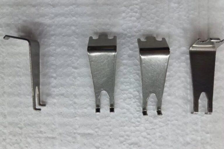
Tape, pocket, and presentation: the quiet saboteurs
However, vision isn’t the only “soft” variable. Tape presentation can wreck you even with a solid library.
Things that flip polarity outcomes without changing your program at all:
- pocket chamfer differences between tape vendors
- cover tape reflection patterns (especially glossy)
- pocket depth and part seating angle (tilt changes what the camera “sees”)
- static cling that lifts a corner of the part
- worn feeder that presents the pocket slightly off datum
I’ve watched a feeder lane that was “good enough” for resistors turn into a polarity nightmare for diodes because the parts didn’t sit flat, which made the mark shadow disappear, which made the algorithm choose the wrong 180° option. That’s not a software bug. That’s physics.
And when someone says, “But we always buy tape from Vendor A,” my first thought is: do you verify that, or do you assume it?
Assumptions cost money. Real money.
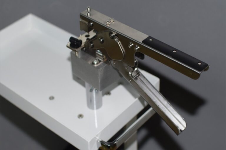
Nozzle rotation calibration: when the machine really is guilty
But yes—sometimes it’s mechanical. And this is where I get blunt with maintenance teams: rotation drift is real, and it’s usually gradual, which makes it dangerous.
Nozzle rotation calibration failures show up like this:
- flips correlate to a specific head, spindle, or nozzle family
- theta looks “close” but not stable across repeats
- the machine passes a quick check, fails under speed
- errors cluster after a nozzle change or after a long run
Why? Wear. Backlash. Slop. Encoder offsets. Nozzle seating.
The rotation train can lose stiffness without screaming. You’ll still place parts. You’ll still hit XY. You’ll just rotate a fraction off… until the vision correction starts compensating… until it compensates the wrong way on a symmetric part… and then you get a clean 180° inversion that everyone blames on “library.”
This is why I push shops to treat calibration like measurement, not “we’ll do it when the line is down.” If your process discipline is loose, the machine becomes an opinion machine.
You want structure? Use it. Keep it visible, keep it enforced, and stop letting it live in one senior tech’s head. Start here: Process Quality resources. And if you’re building a reliable rhythm for wear items and spares, don’t pretend it’s optional: Maintenance & spares planning.
The fast diagnostic path that ends the finger-pointing
So here’s the playbook I use when the room starts getting loud.
Not fancy. Just clean.
- Freeze the variables. Same board. Same program. Same feeder. Same nozzle. Same reel. Same camera settings. Same everything.
- Run a tight sample. Place 20–50 parts onto a scrap PCB or a placement plate. Don’t “eyeball” it. Inspect under a scope. Record orientation.
- Change one thing at a time. If you change two things, you learn nothing. You just create stories.
- Use failure-follow logic.
- Swap nozzle → if the inversion follows the nozzle, your rotation axis or nozzle seating is suspect.
- Swap head/spindle (if possible) → if it follows the head, you’ve got a mechanical calibration or wear problem.
- Swap reel (same MPN, different lot/vendor) → if it follows the reel, your presentation/mark contrast is weak.
- Apply +180° theta offset in the library → if the fix is instant and stable, your library reference is wrong.
- Then lock the fix. This is where teams fail. They “fix” it today and forget to harden it. Two weeks later it’s back.
Question time. Why do you think that happens?
Because nobody owns the root cause. They own the firefight.
What actually reduces polarity flips (in the real world)
Yet the best shops don’t rely on one layer of defense. They stack them:
- Library governance: one person (or one controlled workflow) owns the rotation rules, and changes require review.
- Vision teach discipline: teach using real production reels, not showroom samples.
- Lighting stability: lock exposure/gain profiles, clean lenses, control reflections.
- Feeder qualification: feeders that handle 0201s are not automatically good at polarized mark detection parts.
- AOI gate: AOI must check polarity on polarized references. Not “sometimes.” Always.
If you run high-mix, you can’t depend on memory. If you run high-speed, you can’t depend on luck.
And if operators keep bypassing NG prompts because “it’s probably fine,” you need training that has teeth—plus escalation rules that don’t punish people for stopping the line.
That’s why formal support matters. Not as a brochure. As a system. If you need a real framework, don’t wing it: Training & after-sales support.
What causes the most damage (and who should own the fix)
| Root cause bucket | What it looks like on the line | Quick proof test | Fix that actually holds | Owner |
|---|---|---|---|---|
| Library rotation wrong | Same part flips every time, same angle | Add +180° theta offset and re-run | Rebuild library rule + lock approvals | Process engineering |
| Weak polarity mark vision | Random flips, often lot-to-lot | Change lighting/exposure, re-teach image | Tune vision + add AOI polarity gate | Process + QA |
| Reel/pocket orientation mismatch | Flips start after reel change | Swap reel vendor / lane | Standardize reel spec + incoming check | Materials + QA |
| Nozzle/rotation chain drift | Flips correlate with certain heads/nozzles | Swap nozzle/head | Calibrate rotation + replace worn parts | Maintenance |
| Operator bypass behavior | “It’s fine” culture, NG ignored | Audit logs + first-article discipline | Training + escalation rules | Production |
I’ll say the quiet part loud: the “Owner” column is where good intentions go to die.
You can write a corrective action. You can hold a meeting. You can even add a new checklist. But if you don’t assign one accountable owner with authority to block release, you’ll keep paying the polarity tax forever.
And that tax isn’t small. One inverted diode can mean:
- board rework time (hot air, risk of pad damage, repeat inspection)
- test time wasted
- scrap components
- the slow poison: customer trust erosion
That last one stings more than the scrap.
FAQs
What is a pick and place polarity error?
A pick and place polarity error is when an SMT mounter places a polarized part—like a diode, LED, tantalum, or electrolytic capacitor—with the anode/cathode or +/- orientation reversed relative to the PCB pads, usually because the library angle, vision polarity detection, or tape pocket presentation defines “front” incorrectly even though XY placement is accurate. From my experience, the danger is how normal it looks. The board often sails through quick visual checks because the footprint aligns, the solder wets, and nothing screams until electrical test (or worse, field use). If you’ve ever seen a regulator rail sag under load and blamed the IC, you know this pain. It was the diode. It’s often the diode.
Why do polarized parts get inverted by exactly 180 degrees?
A 180 degree rotation SMT error happens when the machine’s theta reference for the package is ambiguous or misdefined, so the placement system chooses the opposite valid orientation—often caused by symmetric outlines, weak polarity mark contrast, incorrect library zero-angle conventions, or reels that present the part flipped relative to the taught image. Here’s the ugly truth: the machine isn’t “wrong” in the way people mean. It’s consistent with the information you fed it. If the outline match has two equally good answers 180° apart, and your mark detection doesn’t dominate the decision, the system will sometimes pick the wrong one and still feel confident. That confidence is what makes the defect so annoying.
How do I diagnose whether it’s vision, nozzle, or library?
Diagnosing a pick and place polarity error means isolating three interacting layers—library rotation data (theta offsets), mechanical rotation integrity (nozzle/spindle/encoder repeatability), and vision-based theta correction (mark/outlines under your lighting)—by freezing variables, swapping one factor at a time, and tracking whether the inversion follows the nozzle/head, reel/pocket, or the programmed angle definition. Do the boring controlled test. Place 20–50 parts onto a scrap board, inspect, and log. Then swap only the nozzle. Then swap only the reel. Then apply a temporary +180° offset in the library. If the defect follows the nozzle, stop blaming software. If the +180° offset fixes everything immediately, stop blaming mechanics. If it’s lot-to-lot chaos, your mark detection is weak and your lighting is probably lying to you.
What settings reduce polarity marking detection failures?
Polarity marking detection fails when the camera can’t reliably separate the intended mark (stripe/dot/notch) from reflections, mold seams, print variation, or pocket shadows, so improving it usually means stabilizing lighting geometry, exposure/gain, focus, and teach images using real production samples—not just toggling a “polarity” checkbox and hoping the algorithm guesses right on a symmetric outline. I’ve seen teams crank gain until the mark “shows up,” and then wonder why the system starts locking onto glare lines. Don’t do that. Tighten your illumination, reduce specular reflections, use diffuse light where needed, and re-teach with the worst-looking real parts you can find. Also: clean the lens. People laugh at that. Then they stop laughing when the “random” flips vanish after a wipe.
What’s the fastest way to prevent inverted polarized parts in production?
The fastest prevention is to enforce a first-article polarity gate that validates library theta, feeder presentation, and vision mark detection on a real board and real reels, then require AOI to check polarity on every polarized reference before release—because speed without that gate just scales your defect rate faster than you can rework it. If you’re high-mix, this is non-negotiable. Build a “golden board” routine, lock library edits behind review, and force AOI polarity checks on diodes/LEDs/tantalums. If you’re high-speed, add a second layer: periodic rotation verification and nozzle rotation calibration checks so drift doesn’t sneak in mid-run. And if operators can bypass NG prompts, fix that culture (and the system). Otherwise you’re just betting against probability.
Conclusion
If you’re tired of arguing in circles, we can make this boring (in a good way): tighter libraries, cleaner theta rules, calibrated rotation, and a polarity gate that operators can’t quietly bypass. Start with our Service Promise and then Contact us with one example board file, one reel label photo, and your AOI screenshots. We’ll tell you where the inversion is really coming from.